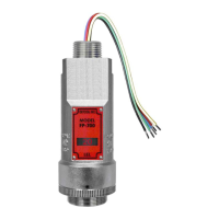
Model FP-700
FP-700 Instruction Manual Rev. 5.1 Page 13 of 46
Customer
Supplied Wiring
(Out to next Device)
(+)
mA
(-)
A(+)
B(-)
Wiring to
Sensor Assembly
Wht
Blu
Red
Grn
Blk
Explosion
Proof
Junction Box
(+)
mA
(-)
A(+)
B(-)
(+)
mA
(-)
A(+)
B(-)
Customer
Supplied Wiring (In)
Modbus RS-485 to
Host Control Device
Power from and 4-20mA
out to Control Device
Install a 100-250 Ohm
resistor if the 4-20mA
output is not used
Modbus RS-485 to
next Device
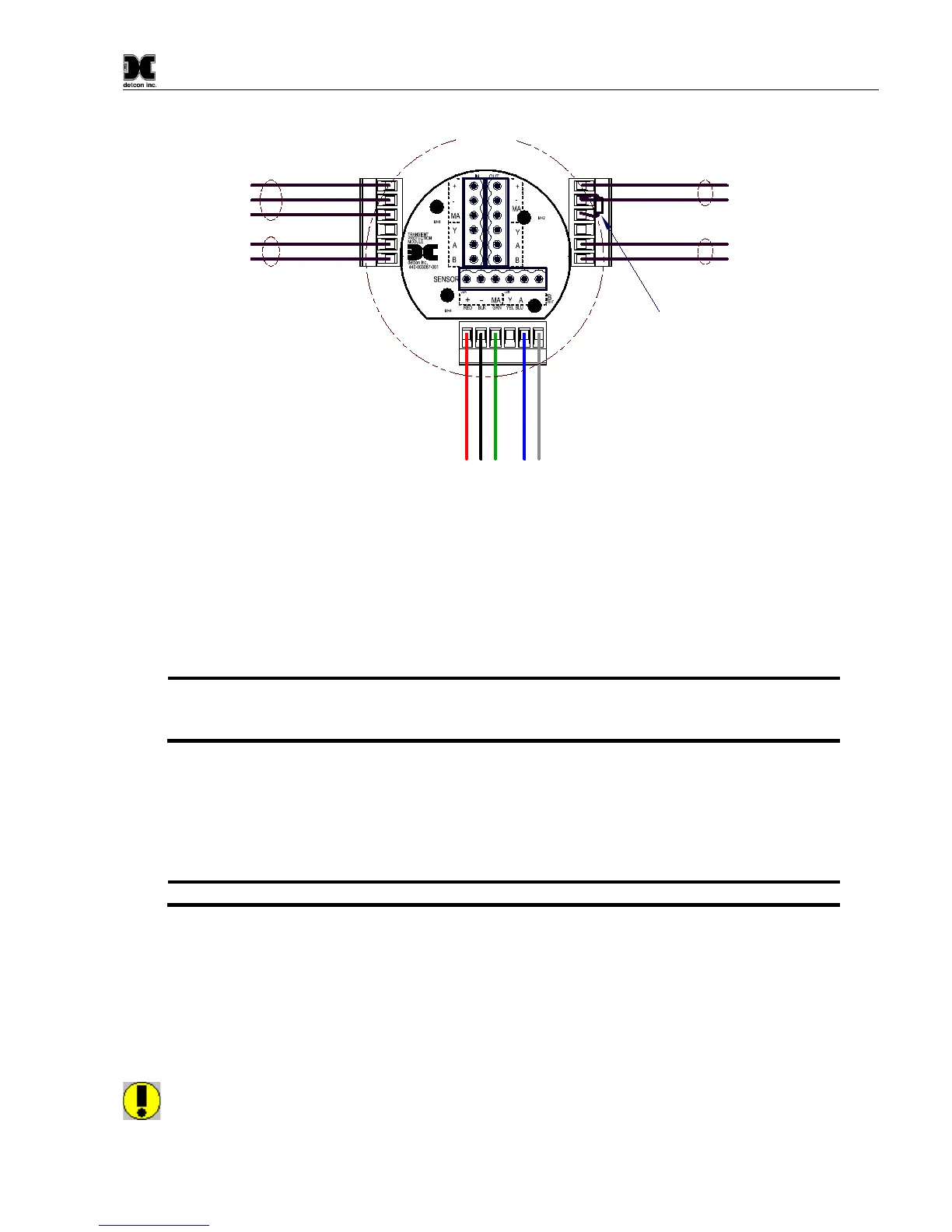
Figure 14 Sensor Wire Connections
a) Remove the junction box cover. Identify the terminal blocks for customer wire connections.
b) Observing correct polarity, terminate the 3-conductor 4-20mA field wiring (+, -, mA) to the sensor assembly
wiring in accordance with the detail shown in Figure 14. If the 4-20mA output is not used, the green wire
from the sensor must be connected to the (-) terminal on the Transient Protection Module.
NOTE: If the 4-20mA output is not being used, the Green wire from the sensor must be
connected to the Black wire at the (-) terminal on the Transient Protection Module to
ensure proper sensor operation.
a) If applicable, terminate the RS-485 serial wiring as shown in Figure 14. Use the second plug (Out) as
termination point on the customer side to facilitate a continuous RS-485 serial loop
The RS-485 (if applicable) requires 24 gauge, two conductor, shielded, twisted pair cable between sensor and
host PC. General Cable Commodore part number ZO16P0022189 is recommended.
NOTE: Install a 120Ω resistor across A & B terminals on the last sensor in the serial loop.
c) Trim all exposed wire leads if they are not permanently landed in the terminal block.
d) Replace the junction box cover.
2.7 Initial Start Up
CAUTION: Do not apply power to the sensor assembly in a hazardous area unless the junction box
cover is tight and all electrical seals have been installed