INSTALLATION, CONT.
Interconnections
All input, output and power connections are made at the bottom rear panel of the indicator.
Refer to Figure No. 1 for the rear panel layout.
Load Cell Connection
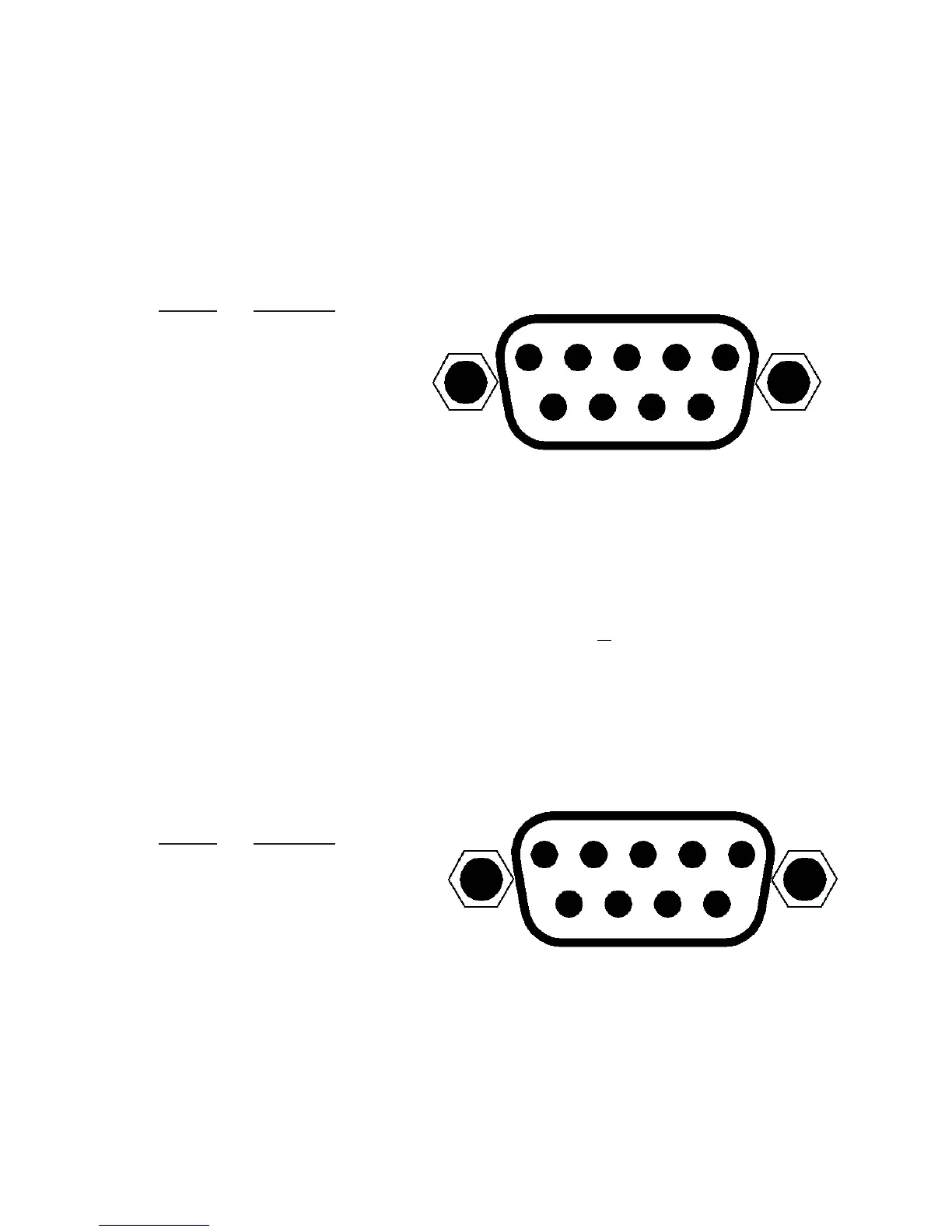
The load cell cable connects to the 750 via a 9-pin "D" connector on the rear panel of the
indicator. Figure No. 4 shows the pin identification for the load cell connector. Make certain
that the pins are correctly identified before soldering a wire to them. Use the connector
retaining screws to hold the load cell cable connector securely to the rear panel.
PIN NO.
FUNCTION
1 +EXCITATION
5 4 3 2 1
2 -SIGNAL
3 no connection
4 no connection
9 8 7 6
5 SHIELD
6 -EXCITATION
7 +SIGNAL
8 no connection
9 no connection Figure No. 4
Serial Interface Specifications
The 750 Serial interface can be configured during the setup and calibration procedure or
during the setup review operation. Using either method, it is possible to select the operation of
the interface.
The serial interface may be connected to a computer for transmission of weight and associated
data to a PC-based EMR (electronic medical record) software program. The data can be
transmitted on demand by pressing the Down Arrow/Print (b/~
) key or on receipt of a
command from the computer. Note that the serial interface can also be connected to a printer
to record weight and associated data.
Serial I/O Port
The 750 RS-232 serial I/O port is a 9-pin "D" connector on the rear panel of the indicator.
Figure No. 5 shows the Serial I/0 connector along with the identity of the pins used. Make
certain that the pins are correctly identified before soldering a wire to them. Use the connector
retaining screws to hold the serial cable connector securely to the rear panel.
1 2 3 4 5
PIN NO.
FUNCTION
2 DATA INPUT (RXD)
6 7 8 9
3 DATA OUTPUT (TXD)
5 SIGNAL GROUND (GND)
Figure No. 5
Note that pins 1, 4 and 6 through 9 are not used.
The 750 RS-232 serial interface can be configured during the setup and calibration procedure
or during the setup review operation. Using either method, it is possible to select the operation
of the serial interface as well as select the baud rate.
x The baud rates supported are: 4800, 9600, 19.2K and 38.4K baud.
x The data format is fixed at 8 bits, No parity, and 1 stop bit.
x The indicator is shipped from the factory with the baud rate set to 9600 baud.
8555-M483-O1 Rev A x 750 Owner’s
5