14
2
26 443 0
21
20
19
18
17
16
15
14
2
3
4
5
6
7
13 12 11 10 9 8
1
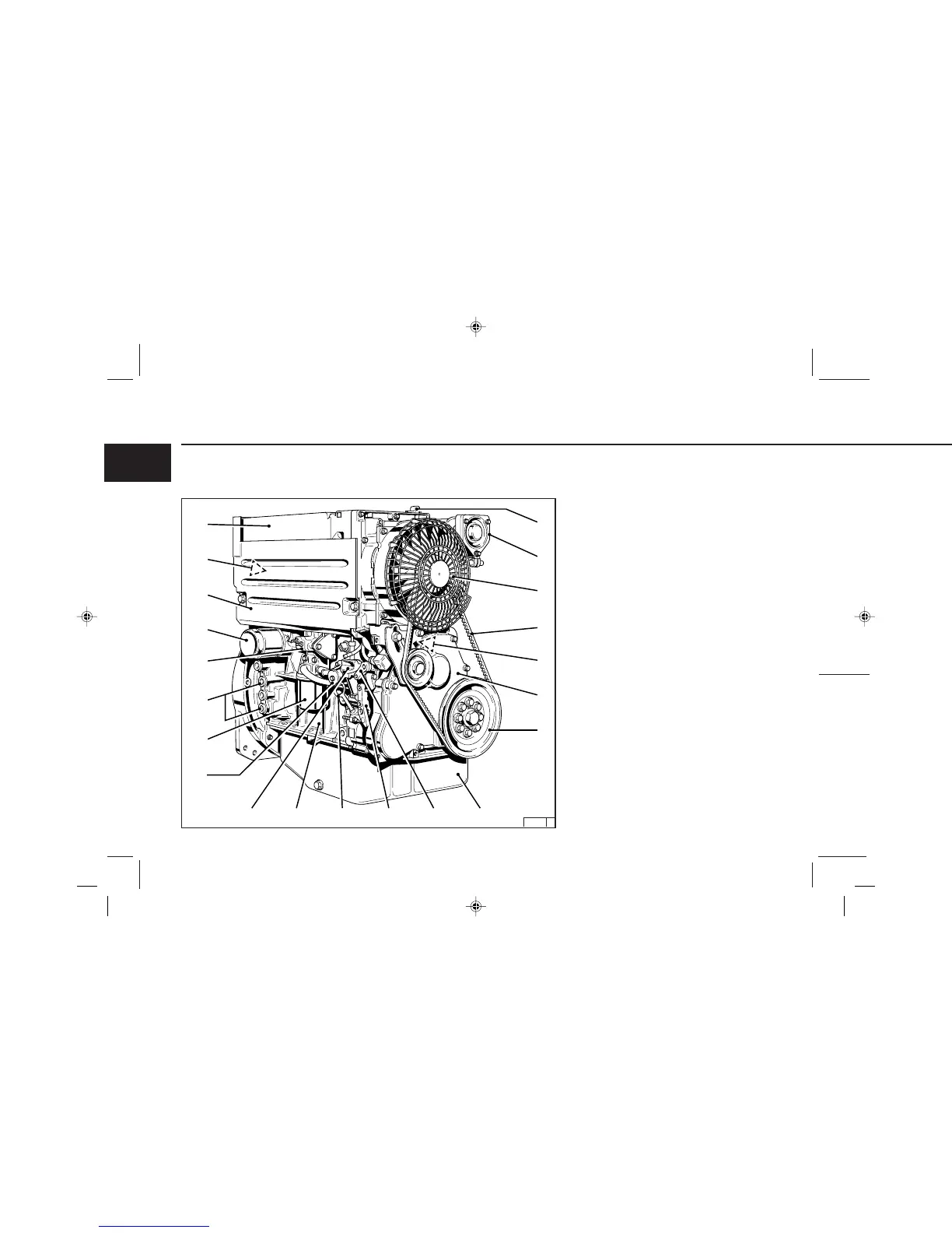
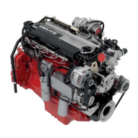
Engine Description
2.2.3 Service Side
BFL 1011F
1 Oil filler neck (valve-gear housing cover)
2 Charge-air line / air-intake line
3 Fan with integrated generator
4 Narrow V-belt
5 Solenoid
6 Wheel-house cover
7 V-belt pulley on crankshaft
8 Oil sump
9 Cut-out handle
10 Speed control lever
11 Oil dipstick
12 Crankshaft housing
13 Oil fill point (on side of crankcase)
14 Fuel pump
15 Easy-change fuel filter
16 Connection facility for oil heater
17 Charge-air pressure full-load stop (LDA)
18 Lube oil easy-change filter
19 Removable coolant intake hood
20 Injection pumps
21 Oil cooler
2.2 Engine Illustrations
7343en_k02_pdf 05.10.1999, 9:21 Uhr14