16
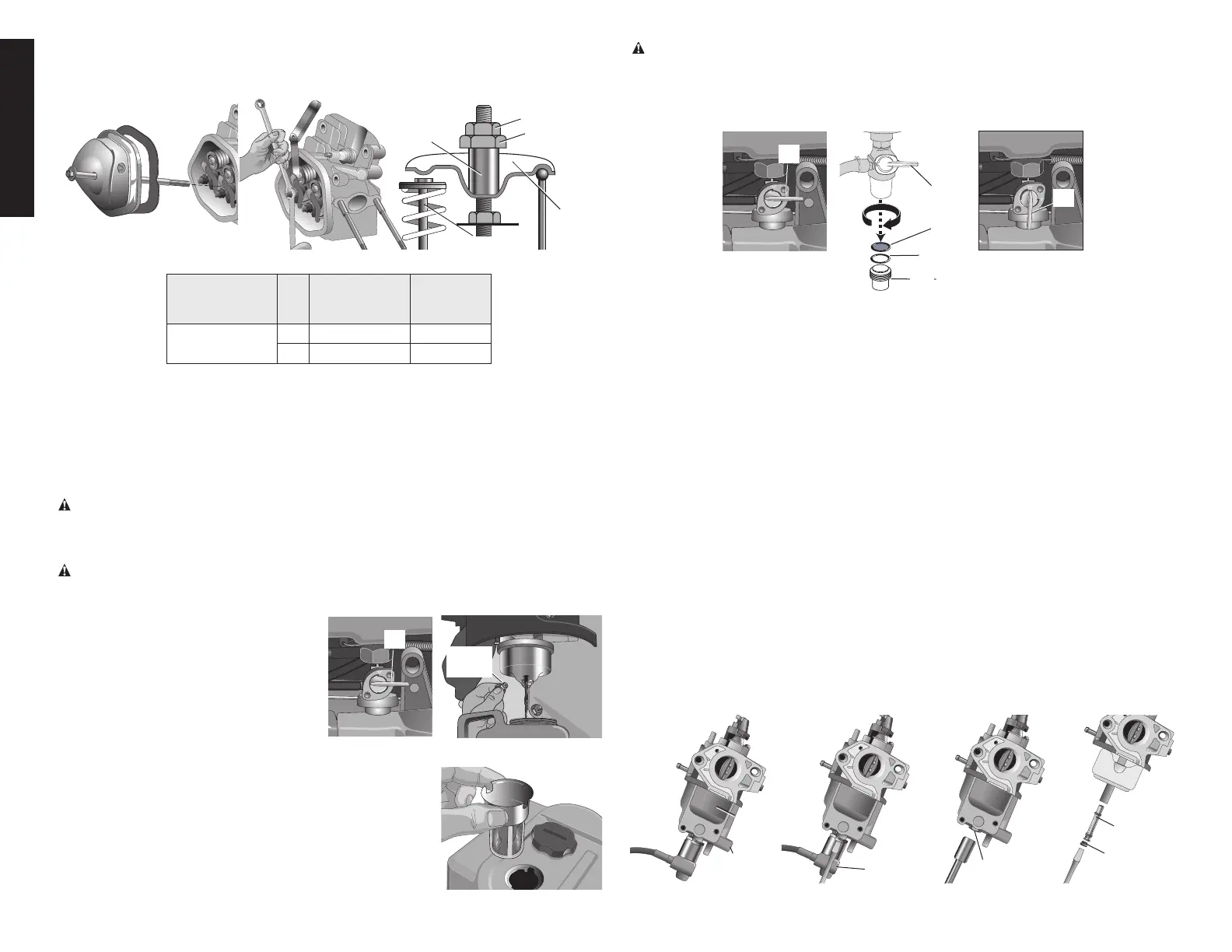
2.Set the piston in the top dead center position of its compression stroke.
NOTE:bothrockerarms(
P7,K8) will have the largest gap with each valve (U7,V7,P8,Q8).
3.Insertafeelergaugebetweentherockerarmandvalvetomeasurevalveclearance.
R7, M8
S7, N8
P7, K8
R10
U7, V7, P8, Q8
Standard
(mm)
Service
Limit
(mm)
VALVE
CLEARANCE
IN
0.10~0.15 -
EX
0.20~0.25 -
4.Adjustrocker armpivot(R7,M8) by loosening the rocker armlocknut (S7, N8)and
adjustthepivotlocknut(R10)untiltheclearanceiscorrect.Whenclearanceiscorrect
tightentherockerarmlocknut.
5.Checktheclearanceagainwithnutstightened.
IMPORTANT: If the engine does not start, is hard to start or is performing poorly ensure
fuelsystemiscleanandfueltankcontainsfreshgasolinebeforetroubleshooting.
WARNING: Risk of explosion.
Spilled gas o line and it’s vapors can be come ignited from
sparks from smoking products, electrical arcing, exhaust, flame, gas es and hot engine com-
ponents such as the muffler.
Make sure there are no sources of ignition, such as smoking
products near servicing location. Wipe any fuel spillage from engine.
WARNING: Hot surfaces. Risk of burn. Engine and surrounding parts are very hot, do
not touch. Allow engine to cool prior to servicing.
DRAIN CARBURETOR
1.Placethefuelshutoffvalve(A,ifequipped)
A
B2, K2,
F3
intheclosed(horizontal) positionas
shown.
2. Place an
OSHA-ap proved con tain er
suitable for fuel under the carburetor
bowl.
NOTE:
Using a funnel will allow
the fuel to flow into the container with
less spillage.
3. Remove the carburetor bowl drain bolt (B2,K2,F3).
4. Fuel will drain from carburetor bowl.
5. Remove the carburetor bowl and clean it in nonflammable
or high flash point solvent.
CLEANING DEBRIS SCREEN (IF EQUIPPED)
1. Remove fuel cap.
2. Remove debris screen.
3.
Clean debris screen. Use compressed air to blow off
debris.
WARNING: When using compressed air, user always must wear eye protection that
conforms to ANSI Z87.1. (CAN/CSA Z94.3).
FUEL SEDIMENT CUP CLEANING (IF EQUIPPED)
1.Place the fuel shut off valve (A, if equipped) in the closed (horizontal) position as
shown.
A
B
A
C
D
A
2.Removethesedimentcup(D)fromthefuelvalveonthebottomofthetank.
3.Cleanthesedimentcup,screen(C)andO-ring(B)innonflammableorhighflashpoint
solvent.
4.Drainandremovegastank,flushuntilclean.
5.Replaceorcleanfuelfilter.Fuelfiltermaybeinsidegastankwherefuelexitsoran
in line fuel filter may be on the fuel line. See
Service Bulletin
(SB06109)
REASSEMBLE
1. Reinstall O-ring, sediment cup, carburetor bowl, carburetor bowl drain bolt, debris
screen and fuel cap
2.Replaceinlinefilter(ifequipped).
3.Turnthefuelshut-offvalve(A,ifequipped)totheopen(vertical)positionandcheckfor
fuelleaks.
High Altitude Modification should only be made to engines operating at above
5,000ft.(1524m)foranextendedperiodasmanufacturedenginesaresuitableforopera-
tionupto5,000ft.(1524m)abovesealevel.NOTE: Reset to factory setting immediately
whenengineismovedtooperatebelow5,000ft.(1524m).Toreset,replacehighaltitude
main jet with low altitude main jet. If the engine is used at low altitudes after a carburetor
modification, the carburetor may cause the engine to overheat and result in serious engine
damage.
1. Set the fuel valve in the off position. Remove the carburetor drain bolt (
B2,K2,F3) from
the carburetor bowl (
E3,J2) and allow fuel to drain into a suitable container.
2. Remove the fuel cutoff solenoid (
D3, if equipped) from the carburetor bowl using a
Phillips screwdriver.
B2,
K2, F3
V3, L2
X2
D3
I4
E3, J2
3. Remove the carburetor bowl (E3,J2)andretainingbolt(V3,L2)witha14mmsocket.