39
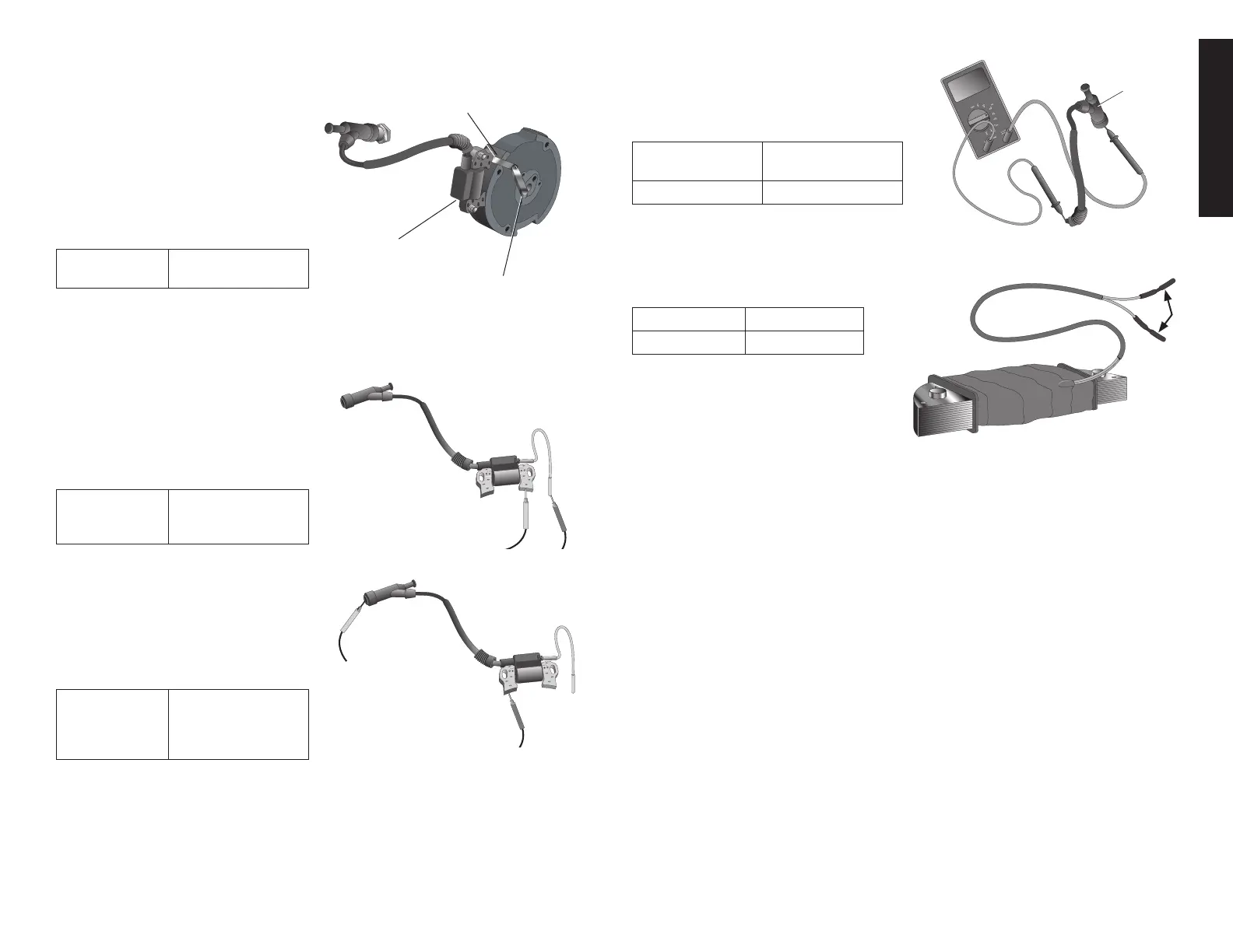
IGNITION COIL AIR GAP
Onlyrequiredwhenignitioncoilorflywheel
C6
I6
THICKNESS GAUGE
has been removed.
1. Loosen the ignition coil bolts.
2.Insert a long thickness gauge or
piece of paper of the proper thick-
nessbetweentheignitioncoil(I6)and
the flywheel (C6). NOTE: Both gaps
should be adjusted simultaneously.
3. Push the ignition coil firmly toward the
flywheel and tighten the bolts.
SPECIFIED
CLEARANCE
0.3-0.5 mm
(0.012-0.020")
4. Remove the thickness gauge.
IGNITION COIL
PRIMARY SIDE
Measure the resistance of the primary
coil:
1. Attach one ohmmeter lead to the
Ignitioncoil'sprimary(black)leadand
Touch the other test lead to the iron
core.
PRIMARY SIDE
RESISTANCE
VALUE
1.3 Ω ± 0.2 Ω
SECONDARY SIDE
Measure the resistance of the secondary
coil:
1.Remove the spark plug boot from
sparkplugandtouchoneohmmeter
lead to the spark plug lead wire and
the other test lead to the coil's iron
core.
SECONDARY
SIDE
RESISTANCE
VALUE
6.4 Ω ±1kΩ
NOTE:Afalsereadingwillresultifthesparkplugbootisnotremoved.
SPARK PLUG BOOT
Measure the resistance of the spark plug
G6
boot.
1. Touch one ohmmeter lead to the wire
endofthecapandtheotheratthespark
plug(G6)end.
RESISTANCE
STANDARD
SERVICE LIMIT
7.5k—12.5k <7.5kor>12.5k
NOTE: Replace the spark plug boot if the
resistance is not within the range specified.
LAMP COIL (IF EQUIPPED)
Measure the resistance between the wire
terminals.
RESISTANCE
12V—15W 0.75 ± 0.1 Ω