48
Crankshaft Bearing
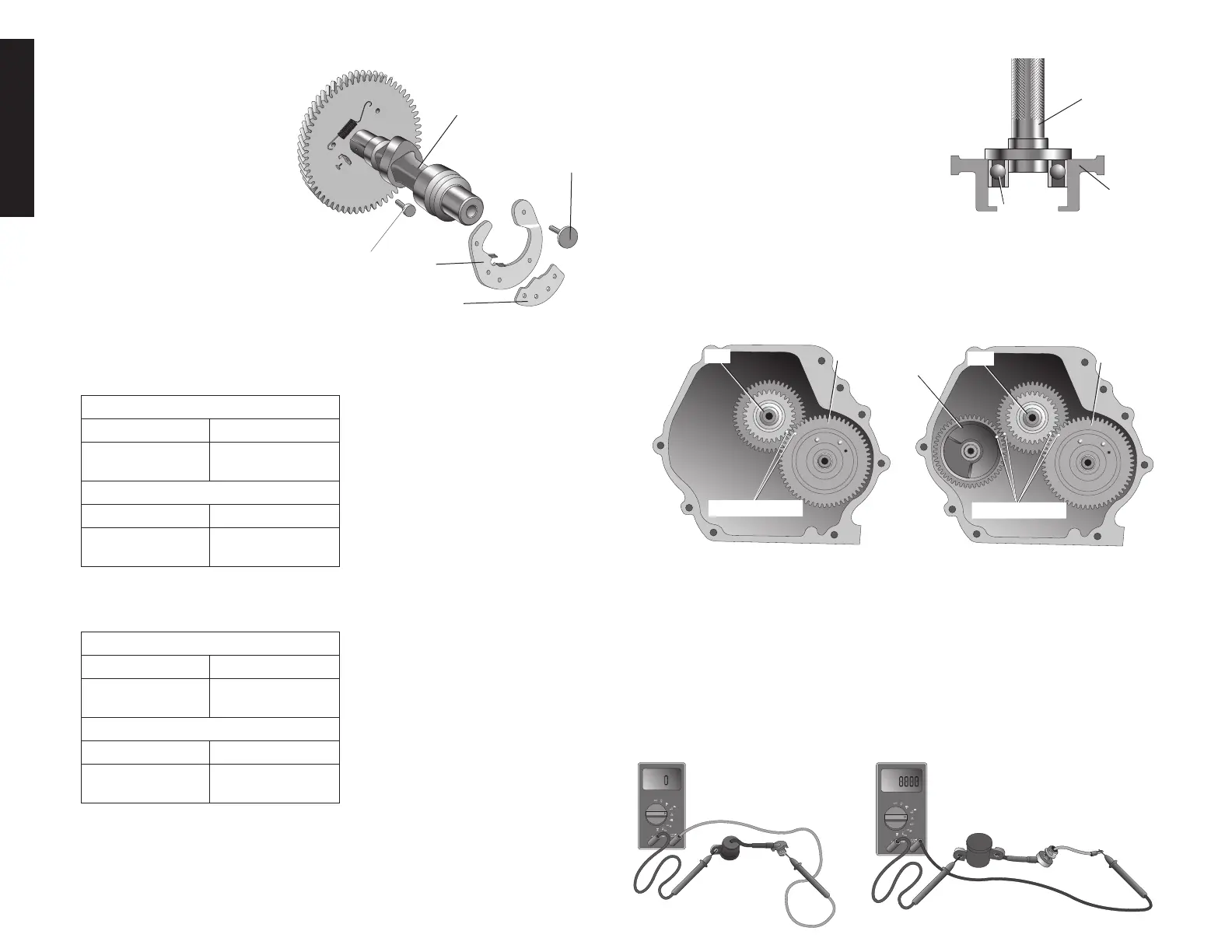
Use a hydraulic press and driver with a diameter
DRIVER
X8
W9
larger than crankcase cover (X8) opening to
press the new bearing (W9) onto the crank-
shaft.
Timing Mark Alignment
NOTE: Balancer gear equipped on DW188F engines only, for DW168F and DW177F
engines proceed to step 2.
1.Withcrankshaft(X9)installedincrankcaseinstallbalancer(A10).NOTE:Alignmarks
onbalancerandbalancerdrivegearofcrankshaft.
2.Install the camshaft aligning marks on camshaft (Y9) with those on timing gear of
crankshaft.
Y9
X9
ALIGN MARKS
DW188F
Y9
X9
ALIGN MARKS
DW168F, DW177F
X10
OIL LEVEL SWITCH (DW177, DW188)
1. With the switch in the normal upright orientation test the continuity between the yellow
lead and the face of the brass ground connector as show. The ohm meter should read
approximately zero resistance.
2. Hold the switch upside down to simulate the float’s position in the crankcase when it is
filled with oil. Test the continuity in the same way between the face of the brass ground
connector and the yellow lead. The ohm meter should read approximately infinite
resistance.
3. If either test yields an incorrect reading replace the low oil shutdown unit.
Y9. Camshaft
Y9
C10
F10
E10
D10
C10. Reducer pin
E10. Flyingblock
D10. Matchingblock
F10. Flyingblockpin
REASSEMBLY
Timing Gear
Usetheoldgearasreferenceandmakeamarkatthesamepositiononthenewgear.
Useahydraulicpress,driverandattachmentI.D.(specialtool)topressthenewgearonto
thecrankshaft.
DW168
Driver 40 mm I.D. 07746 – 0030100
Attachment,
25 mm I.D.
07746 – 0030200
DW177 and DW188
Driver 40 mm I.D. 07746 – 0030100
Attachment,
30 mm I.D.
07746 – 0030300
Governor Drive Gear
Useahydraulicpress,driverandattachmentI.D.(specialtool)topressthenewgovernor
drivegearontothecrankshaft.
DW168
Driver 40 mm I.D. 07746 – 0030100
Attachment,
30 mm I.D.
07746 – 0030300
DW177 and DW188
Driver 40 mm I.D. 07746 – 0030100
Attachment,
35 mm I.D.
07746 – 0030400