Transmitters 9 November 2001 111
Next Chapter
Tran sm it te r
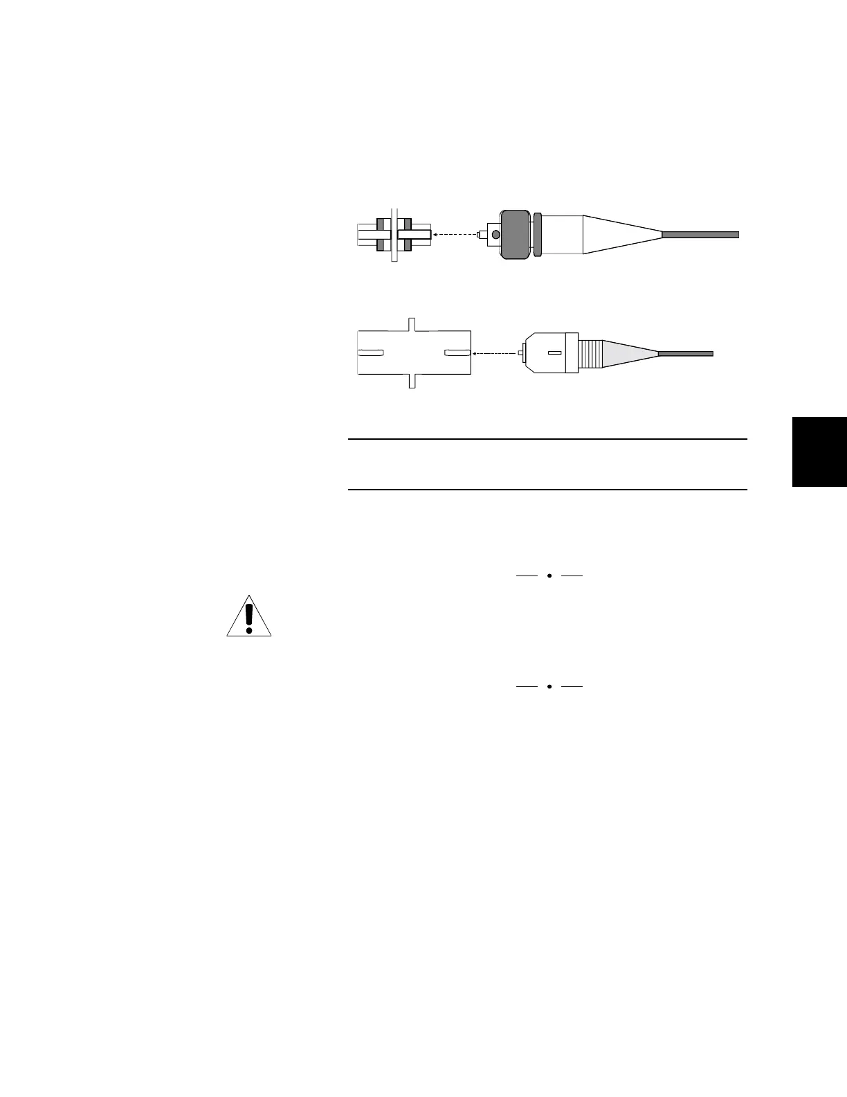
5. Align the key on the fiber’s connector with the bulkhead’s
slot, and slide the connector into the bulkhead until it
locks. For an FC-type, screw the connector to tighten it.
(See Figure 50.)
6. Reinstall the shield, making sure to tighten the screws.
Note: The laser operates only when the shield is installed.
NOTE
It may be desirable to route fiber that is connected to
transmitters in slots 3 – 5 to the left and fiber connected to
transmitters in slots 6 – 9 to the right.
7. Place the fiber in the fiber-management tray.
Fiber may be routed out through either end of the
fiber-management tray; however, do not allow fibers to
cross one another. (Note that Figure 51 shows all fiber
routed in one direction. Fiber may also be routed to both
right and left as long as fibers do not cross.)
Use the plastic clamps mounted inside the tray to bundle
the fiber loosely together. Leave enough slack so that
fibers are not pulled when you lower the fiber-manage-
ment tray.
Figure 50. Optical Connectors
Align the key on the connector with the slot on the bulkhead.
FC Bulkhead
SC Bulkhead
FC Connector
SC Connector