About the development board Connectors and blocks
Digi Connect ME, Wi-ME, ME 9210, Wi-ME 9210 Hardware Reference Manual
24
RS232-enable pin header, P5
P5 is used to enable or disable serial port RS232s transceiver. Shorting P5 pins 1 and 2 will enable the
RS232 transceiver. Shorting P5 pins 2 and 3 will disable the RS232 transceiver.
GPIO port, P7
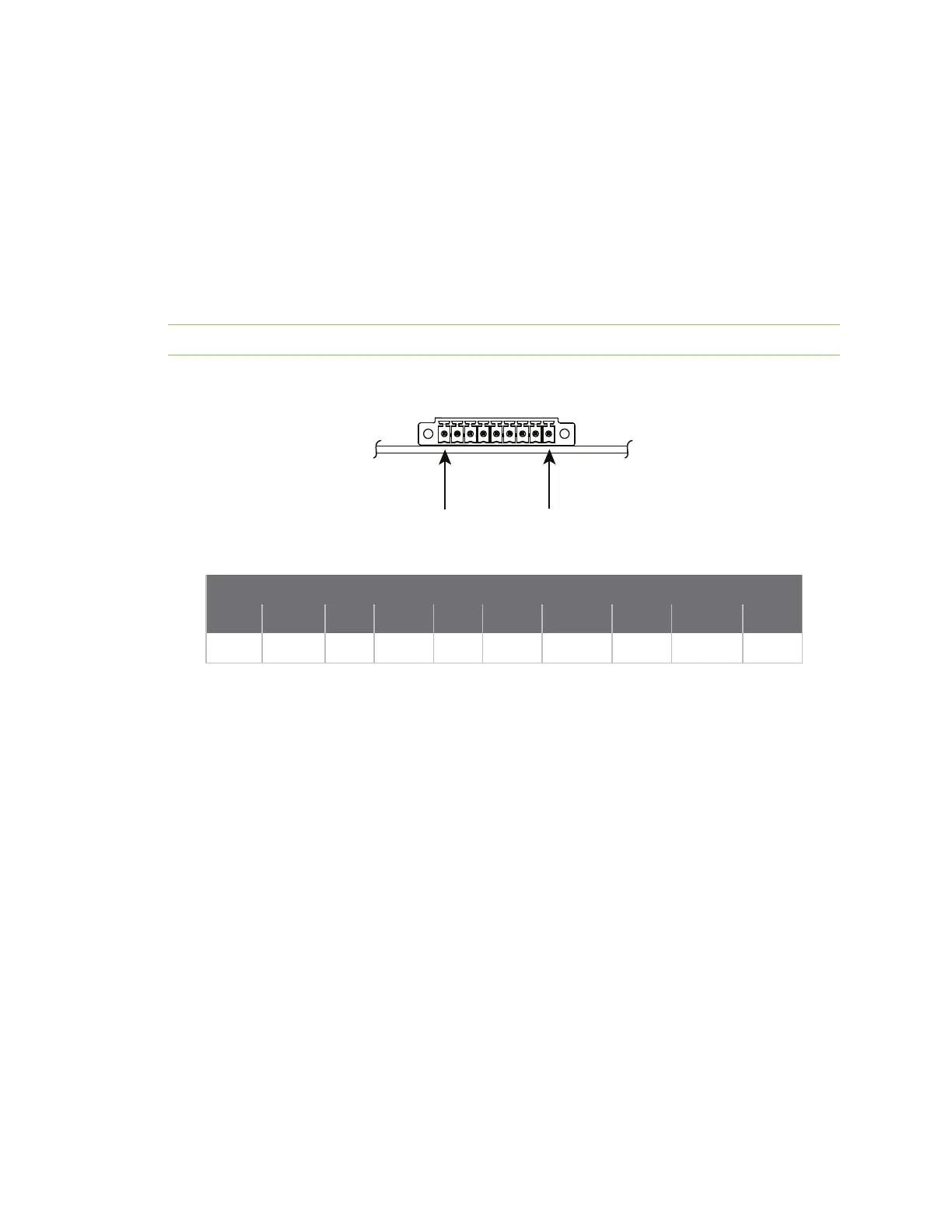
The GPIO port is a 9-pin male right-angle connector that is labeled as P7 on the development board.
See the following figure for pin orientation; see the following tables for pin assignments. For input and
output threshold specifications, see DC characteristics. Note that each signal has a 220 ohm series
resistor between the P7 pin and the module (except GND).
Note The development board is shipped with a 9-pin screw-flange plug attached to the GPIO port.
GPIO port pin orientation
GPIO Port Pin Assignments
Pin 1 Pin 2 Pin 3 Pin 4 Pin 5 Pin 6 Pin 7 Pin 8 Pin 9
Signal GPIO-1 GND GPIO-2 GND GPIO-3 TXD_TTL GPIO-4 RXD_TTL GPIO-5
Connectors and blocks
The development board provides the following connectors and blocks:
n Embedded module connector, P10
n The Digi Connect Wi-ME module does not provide pins 1-6.
n JTAG debugger connector, P12
n -48V DC input to PoE module (Digi Connect ME must be connected to a Powering Device for this
feature.), P13
n 12V DC output from PoE module into Dev Board Power Supply, P14
n Logic analyzer header, P3
See the figure titled Board layout and connector locations for the location of the connectors and
blocks. The following sections describe the connectors and blocks.
Embedded module connector, P10
The Digi Connect ME embedded module connector is a 20-pin female vertical header that is labeled
P10 on the development board. See the following figure for pin orientation; see the following table for
pin assignments.
 Loading...