Contents
About this document
Scope of the reference manual 7
Related documentation 7
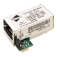
About the Digi Connect ME family of embedded modules
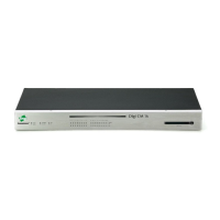
Digi Connect ME and Wi-ME embedded modules 9
Types of modules 9
Connectors: power and device interface 11
Difference in pin assignments/availability 11
Power and device interface connector 11
Connectors: module JTAG interface 13
JTAG interface connectors 13
Connectors: Ethernet interface 15
Ethernet interface pin orientation 15
JTAG jumper 15
Hard reset 16
Connectors: antenna 16
Module LEDs 16
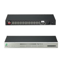
About the development board
Basic description 19
Board layout and connector locations 20
Placement of module 22
Port descriptions 22
Primary serial port, P1 22
Secondary serial port, P2 23
RS232-enable pin header, P5 24
GPIO port, P7 24
Connectors and blocks 24
Embedded module connector, P10 24
Module JTAG interface connector, P11 26
JTAG debugger connector, P12 27
Logic analyzer header, P3 28
Switches and push buttons 29
GPIO switch bank 1, SW3 29
User push button 1, SW1 29
User push button 2, SW2 29
Reset, SW4 29
Digi Connect ME, Wi-ME, ME 9210, Wi-ME 9210 Hardware Reference Manual
4
 Loading...