About the development board Connectors and blocks
Digi Connect ME, Wi-ME, ME 9210, Wi-ME 9210 Hardware Reference Manual
26
Power and Device Interface Connector Pin Assignments
Signal
Description
ME Wi-ME
Pin
# Function
Pin
# Function
15 +3.3V 9 +3.3V Power
16 GND 10 GND Ground
17,
18
11,
12
Not accessible with Digi Plug-and-Play Firmware.
If using a development kit, see Module pinout for
detailed IO configuration information.
19 13 Reserved. Do not connect.
20 /INIT 14 /INIT Software Reset
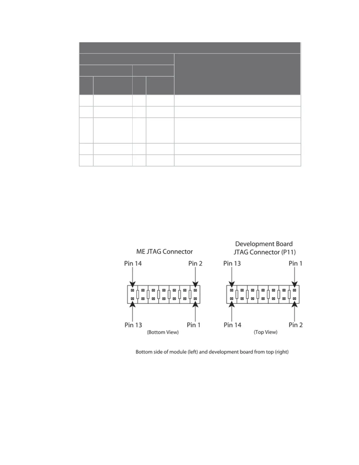
Module JTAG interface connector, P11
The Module’s JTAG Interface Connector is a 14-pin female vertical header that is labeled P11 on the
development board. The connector mates with the JTAG connector on the embedded module. The
Module’s JTAG Connector pins are tied to the debugger connector (see JTAG debugger connector, P12.
Since the modules' JTAG connectors are mounted on the bottom side of the modules, the pin 1
location is mirrored from that of the Development board's mating JTAG connector (P11). The resulting
pin mapping is indicated in the Module JTAG Interface Connector Pin Assignments table below.
 Loading...