PYKO-out: Professional IP audio endpoint
13. ANNEXE F: GPIO CONNECTORS
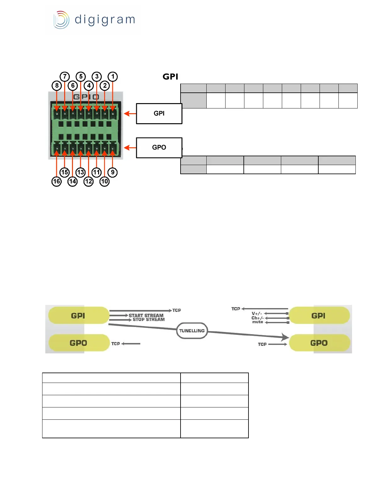
PYKO-out features four TTL 5 V compatible GPIs and four relay GPOs. The counterparts are provided.
GPI pinout
General Purpose Inputs (GPIs)
The state of a GPI can be either “1” or “0”. It is read at “0” as soon as it is connected to the ground
(GND). Otherwise it is read “1”.
Note: Each GPI can receive an external command contact.
General Purpose Outputs (GPOs)
The PYKO-out GPOs are relay outputs. They feature two pins each and are all configured the same
way. Pins 9 & 10 belong to GPO # 1, 11 & 12 to GPO # 2, 13 & 14 to GPO # 3, and 15 & 16 to GPO
#°4.
If written at “1”, the GPO closes the linked relay. If written at “0”, the GPO opens the linked relay.
GPIOs can be used for tunneling from one PYKO towards another (GPIn-> GPOn).
GPO relay specifications