Copyright Digilent, Inc. All rights reserved.
Other product and company names mentioned may be trademarks of their respective owners.
#pragma config POSCMOD = XT
#pragma config OSCIOFNC = ON
#pragma config FPBDIV = DIV_1
#pragma config FPLLIDIV = DIV_2
#pragma config FPLLMUL = MUL_20
#pragma config FPLLODIV = DIV_1
2 Power Supplies
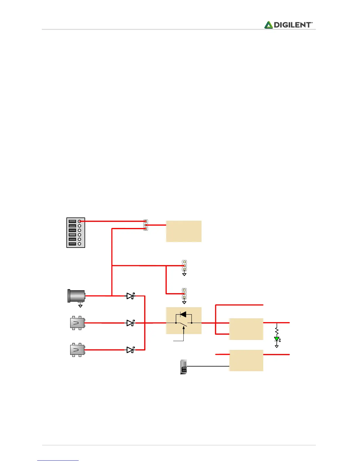
The Basys MX3 requires a 5V power source to operate. This power source can come from the Programming /
Debugging USB port (J12), the USB-UART (J10), or from an external 5V DC power supply that’s connected to Power
Jack (J11). These three power inputs are connected through Schottky diodes to form the primary input power
network, VIN, which is used to power the onboard regulators and the majority of the onboard peripherals. No
jumper is required to select the input power source. The board will automatically power on while the Power Switch
(SW8) is in the on position and power is present on any of the power inputs.
A power-good LED (LD11), driven by the output of the 3.3V regulator (LMR10515), indicates that the board is
receiving power and that the onboard supplies are functioning as expected. An overview of the Basys MX3 power
circuit is shown in Fig 2.1.
Figure 2.1. Power supply circuit.
The USB port(s) can deliver enough power for most designs; however, a few demanding applications, including any
that drive multiple peripheral boards, may require more power than a USB port can provide. In these instances, an
external power supply can be used. Due to their high current demands, motors and servos cannot be powered
through either of the USB ports, and may only be powered through an external supply.