Copyright Digilent, Inc. All rights reserved.
Other product and company names mentioned may be trademarks of their respective owners.
Although ESD protection is provided between the connector pins and the microcontroller pins, ESD safe handling
procedures should be followed when handling the circuit board. The pins on the microcontroller and other circuits
on the board are exposed and can be damaged through ESD when handling the board.
Digilent Pmods can either be plugged directly into the connectors on the Basys MX3 or attached via cables.
Digilent has a variety of Pmod cables available.
You can read more details about the Digilent Pmod Interface Specification from the most recent specification
document, available on the Digilent Pmod Wiki.
21 Analog Discovery Debug Header
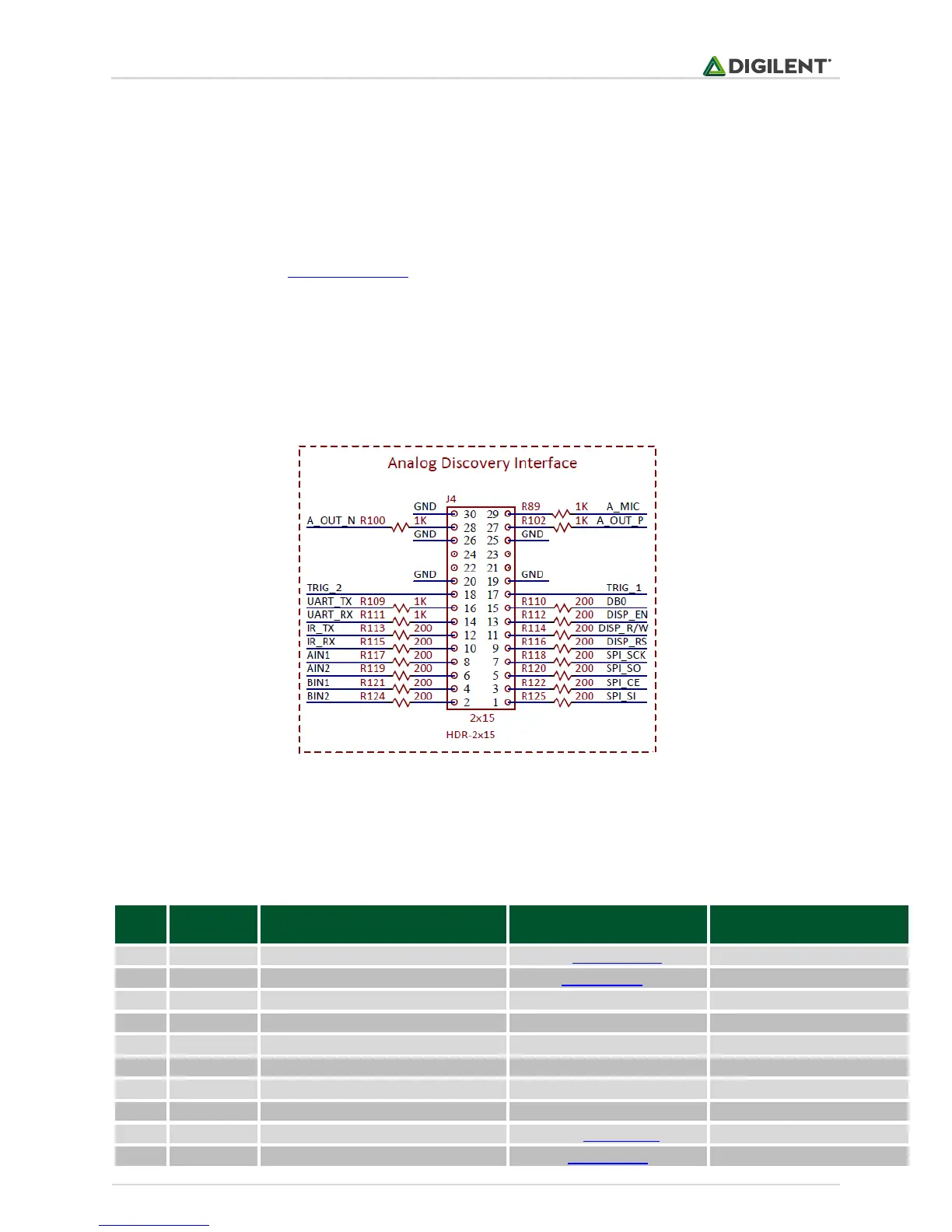
The Basys MX3 board provides a 2x15 Debug Header, exposing some pins that allow key onboard peripheral
signals to be visualized with an oscilloscope or logic analyzer.
Figure 21.1. Debug header schematic diagram.
The connector is designed to match the Analog Discovery and OpenScope connectors, but the pins can be used
with other tools as well.
Table 21.1 below shows the signals exposed by this connector.