Copyright Digilent, Inc. All rights reserved.
Other product and company names mentioned may be trademarks of their respective owners.
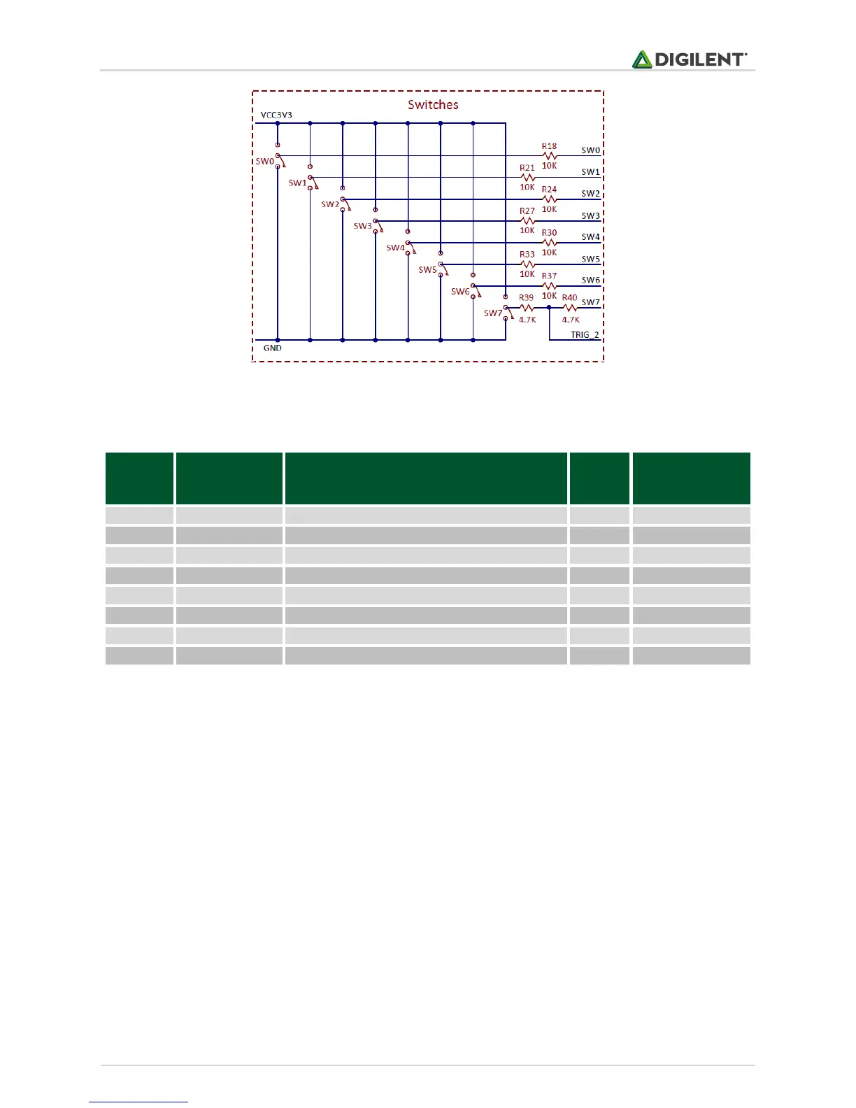
Table 4.1. Switches connectivity.
All the pins must be defined as digital input: their corresponding TRIS bit must be set to 1, and analog function
must be disabled for pins routed to SW5, SW6, and SW7.
TRISFbits.TRISF3 = 1; // RF3 (SW0) configured as input
TRISFbits.TRISF5 = 1; // RF5 (SW1) configured as input
TRISFbits.TRISF4 = 1; // RF4 (SW2) configured as input
TRISDbits.TRISD15 = 1; // RD15 (SW3) configured as input
TRISDbits.TRISD14 = 1; // RD14 (SW4) configured as input
TRISBbits.TRISB11 = 1; // RB11 (SW5) configured as input
ANSELBbits.ANSB11 = 0; // RB11 (SW5) disabled analog
TRISBbits.TRISB10 = 1; // RB10 (SW6) configured as input
ANSELBbits.ANSB10 = 0; // RB10 (SW6) disabled analog