Copyright Digilent, Inc. All rights reserved.
Other product and company names mentioned may be trademarks of their respective owners.
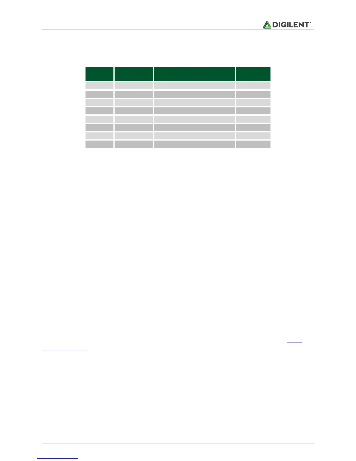
Table 3.1. LED connectivity.
All the pins must be defined as digital output (their corresponding TRIS bit must be set to 0):
TRISAbits.TRISA<0-7> = 0; // LED<0-7> configured as output
3.2 Functionality
To turn an LED on or off, turn the corresponding digital output pin high or low by writing 1 or 0 to the
corresponding LATA register bit.
LATAbits.LATA<0-7> = 1; // turn led on
or
LATAbits.LATA<0-7> = 0; // turn led off
Library functions for using the LEDs are contained in the Basys MX3 library pack, LED library; however, the user can
easily use the LEDs without the LED library, as presented above.
4 User Switches
Eight switches are provided, labeled SW0 – SW7 on the board and in the schematic, attached to eight digital I/O
pins of the PIC32. Reading the switches is done by basic access to an input I/O pin. Read more details in Digital
Inputs and Outputs section.
Figure 4.1 shows the way the switches are electrically connected on the Basys MX3.