Copyright Digilent, Inc. All rights reserved.
Other product and company names mentioned may be trademarks of their respective owners.
The SPI_CE, SPI_SCK, and SPI_SI pins should be configured as digital output, while the SPI_SO pin must be
configured as digital input.
Table 12.2. Flash connectivity.
12.2 Functionality
To use the flash memory, the SPI pins must be properly configured to implement SPI1 functions (see Section 12.1
above). Then, proper SPI communication (read, write) must be implemented over SPI1. The SPI1 interface must be
initialized and then accessed through read and write functions.
Flash communication is implemented in the SPIFLASH library of the Basys MX3 library pack. If a user wants to use
the SPI flash without the SPIFLASH library, they must implement their own SPI functions.
Note that users can visualize the communication with the SPI flash using a connector labeled SPI (J6), located on
the back of the board under PMOD A connector.
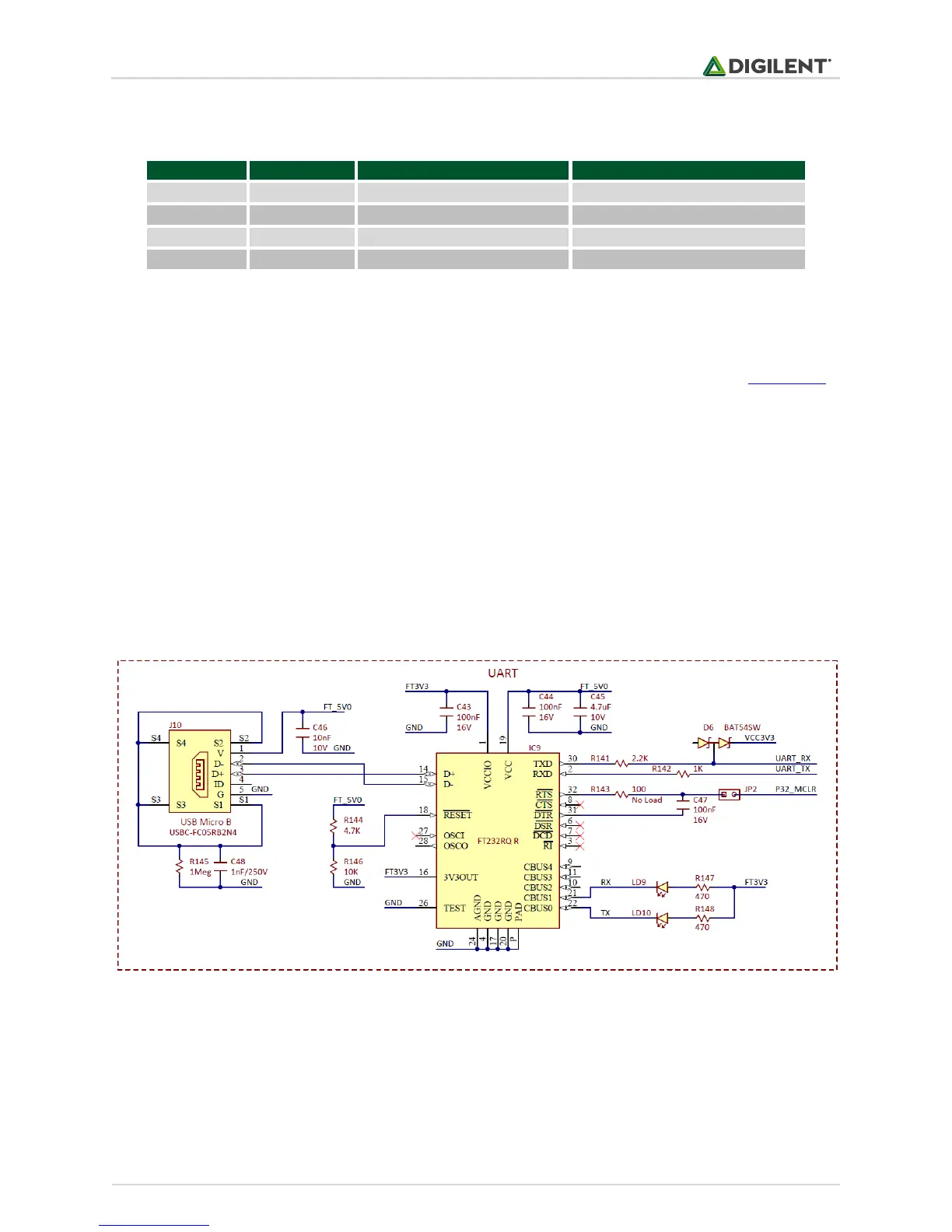
13 UART
Figure 13.1. UART schematic diagram.
The PIC32MX370F512L microcontroller provides five UART interfaces: UART1, UART2, …, UART5. Each UART can
provide either a 2-wire or a 4-wire asynchronous serial interface. The 2-wire interface uses only receive (RX) and
transmit (TX) signals. The 4-wire interface includes request-to-send (RTS) and clear-to-send (CTS) in addition to
receive and transmit signals.