Copyright Digilent, Inc. All rights reserved.
Other product and company names mentioned may be trademarks of their respective owners.
Table 11.1. SPI connectivity.
Communication over the SPI2 interface is implemented in the SPIJA library of the Basys MX3 library pack. If the
user wants to use the SPI2 without the SPIJA library, they must define their own SPI functions.
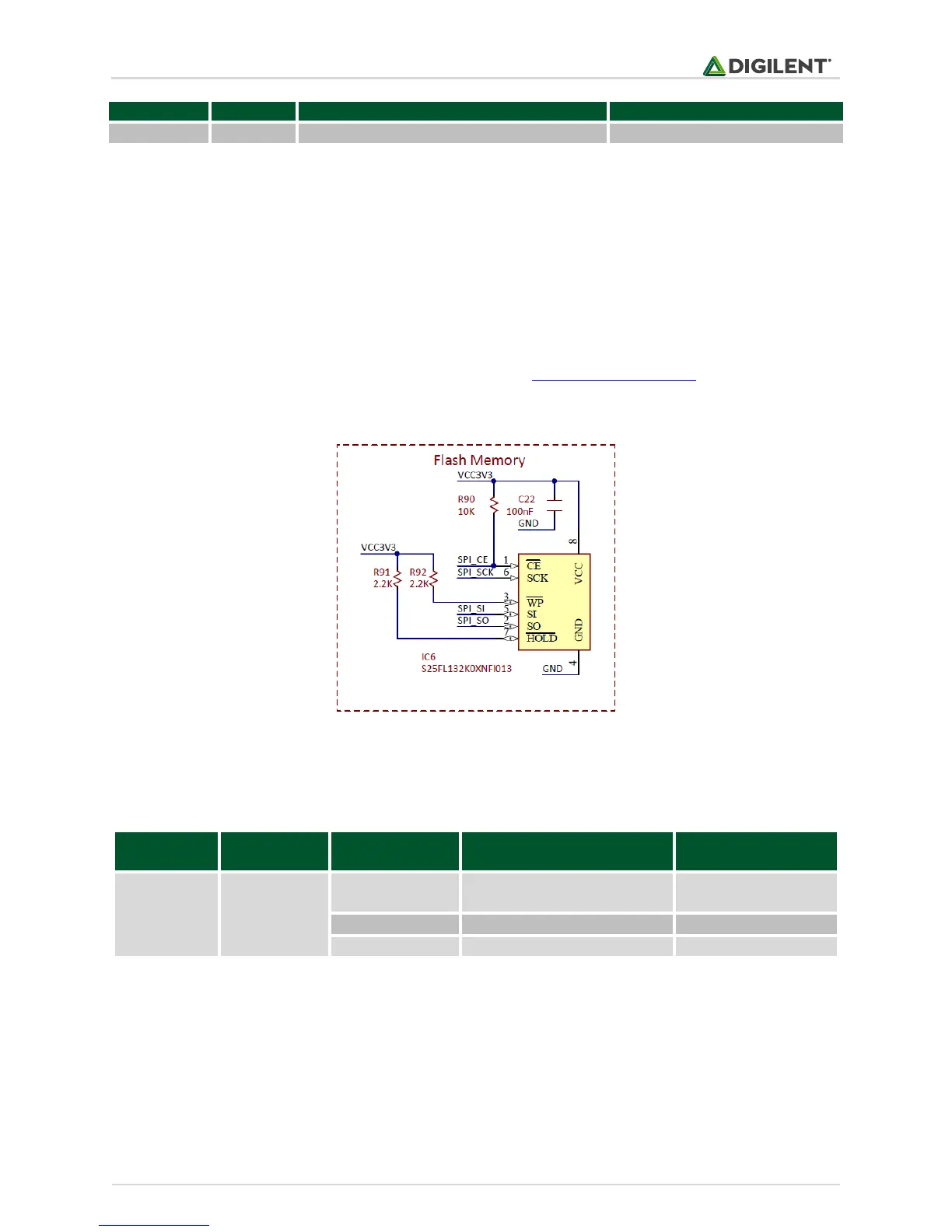
12 Flash Memory
The Basys MX3 comes with 4 MB of onboard flash memory. The part used is the Spansion S25FL132 and is an SPI
memory. More information about the SPI interface is found in the Serial Peripheral Interface section.
Figure 12.1 depicts the way the Flash memory is controlled by digital signals.
Figure 12.1. Flash memory schematic diagram.
It contains 1024 sectors of 4 KB, making the total capacity 4MB. The following table, shown in Table 12.1 extracted
from the S25FL132K datasheet, shows the main memory address map.
Table 12.1. Flash address map.
Please read the S25FL132K documentation for more details.
12.1 Connectivity
The flash memory is connected to the following pins that provide access to the SPI1 interface. Note that RF2
(SPI_SI) and RF7 (SPI_SO) need to be remapped to perform SDO1 and SDI1 functions.