Copyright Digilent, Inc. All rights reserved.
Other product and company names mentioned may be trademarks of their respective owners.
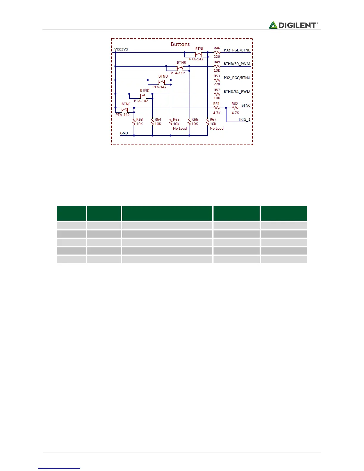
Figure 5.1. Button schematic diagram.
The Basys MX3 also has a red button labeled RESET. This button is connected directly to the MCLR pin of the PIC32
and will trigger it to be reset.
5.1 Connectivity
Table 5.1. Button connectivity.
All the pins must be defined as digital input: their corresponding TRIS bit must be set to 1, and analog function
must be disabled for pins corresponding to BTNU, BTNL, BTNR, BTND.
TRISBbits.TRISB1 = 1; // RB1 (BTNU) configured as input
ANSELBbits.ANSB1 = 0; // RB1 (BTNU) disabled analog
TRISBbits.TRISB0 = 1; // RB1 (BTNL) configured as input
ANSELBbits.ANSB0 = 0; // RB1 (BTNL) disabled analog
TRISFbits.TRISF4 = 1; // RF0 (BTNC) configured as input
TRISBbits.TRISB8 = 1; // RB8 (BTNR) configured as input
ANSELBbits.ANSB8 = 0; // RB8 (BTNR) disabled analog
TRISAbits.TRISA15 = 1; // RA15 (BTND) configured as input
5.2 Functionality
To read the buttons, the user needs to read the corresponding digital input pin, a value of 1 indicating the button is
pressed or 0 indicating the button is released: