Copyright Digilent, Inc. All rights reserved.
Other product and company names mentioned may be trademarks of their respective owners.
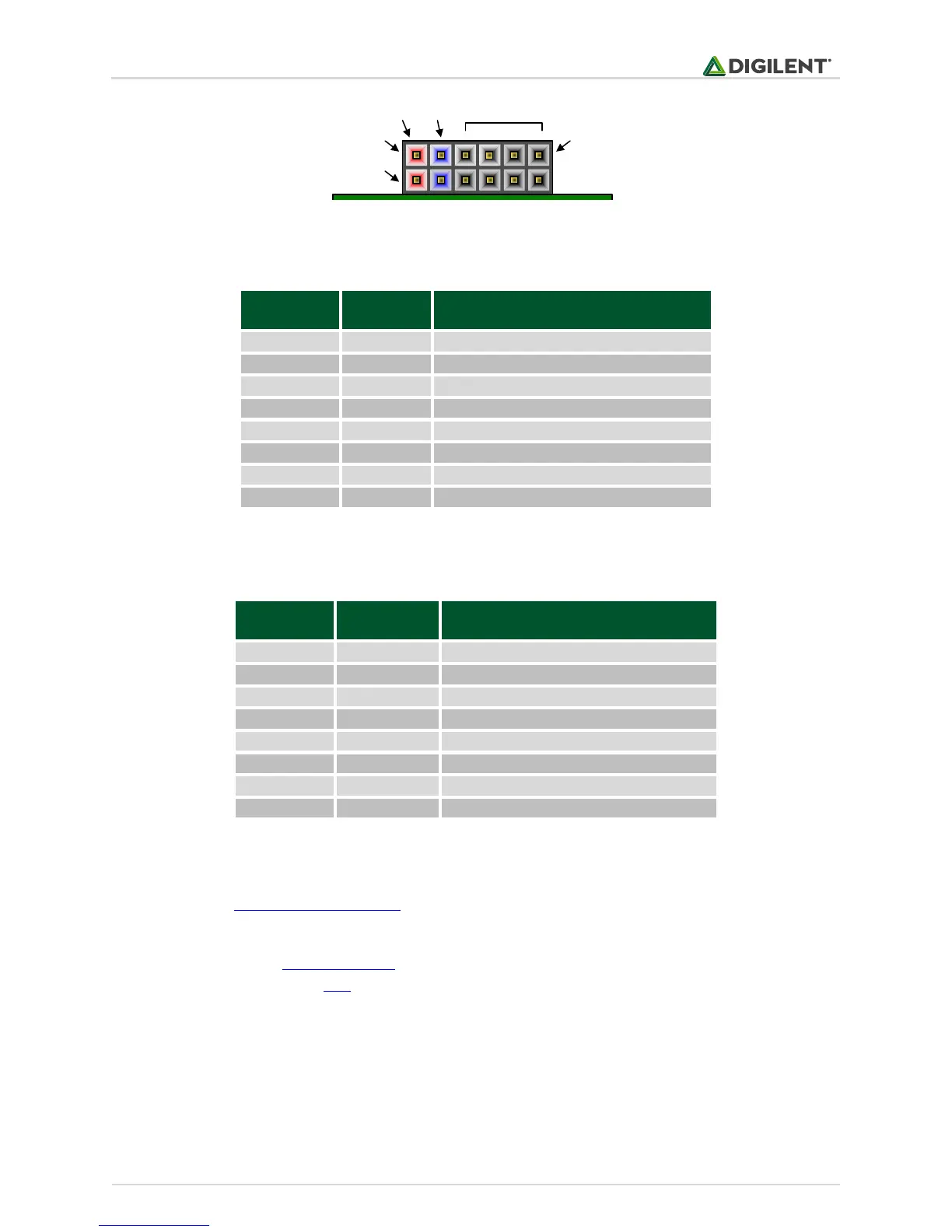
Figure 20.2. Pmod connectors: front view, as loaded on PCB.
Table 20.1 summarizes the content of PMODA connector.
Table 20.2. Pmod B pinout.
The signals going to Pmod connectors are also connected to input/output pins on the PIC32 microcontroller.
Review Section 1.3 Digital Inputs and Outputs for more details regarding digital I/Os.
Instead of using the Pmod pins as regular digital input/output pins, the pins can be mapped to several peripherals,
as explained in Section 1.4 Remappable pins. For example, the SPI2 interface is implemented over the PMODA
pins, as explained in Section 11.2 SPI2.
In the above tables, the highlighted pins are 5V tolerant pins. It is safe to apply 5V logic signals directly to these
pins without risk of damage to the microcontroller. All other pins support 3.3V only.
Each pin has a 200-ohm series resistor and an ESD protection diode. The series resistor provides short circuit
protection to prevent damaging the I/O block in the microcontroller if the pin is inadvertently shorted to VDD or
GND, or two outputs are shorted together. The ESD protection diode protects the I/O block from damage due to
electro-static discharge.