Basys MX3™ Board Reference Manual
Copyright Digilent, Inc. All rights reserved.
Other product and company names mentioned may be trademarks of their respective owners.
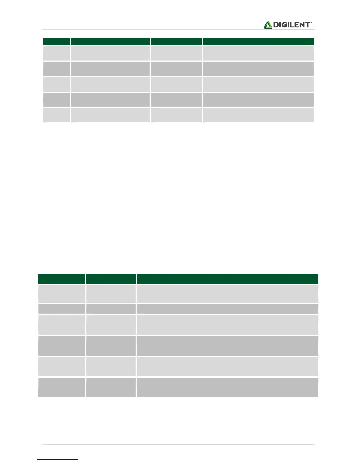
logic low selects IN/IN mode
logic high selects PH/EN mode
IN/IN mode: Logic high sets AOUT1 high
PH/EN mode: Sets direction of H-bridge A
IN/IN mode: Logic high sets AOUT2 high
PH/EN mode: Logic high enables H-bridge A
IN/IN mode: Logic high sets BOUT1 high
PH/EN mode: Sets direction of H-bridge B
IN/IN mode: Logic high sets BOUT2 high
PH/EN mode: Logic high enables H-bridge B
Table 14.2. Motor connectivity.
The command pins (MODE, AIN1, AIN2, BIN1, BIN2) must be defined as digital output and the analog functionality
for AIN1 and BIN2 disabled:
TRISFbits.TRISF1 = 0; //set RF1 (MODE) to be an output
TRISBbits.TRISB3 = 0; //set RB3 (AIN1) to be an output
ANSELBbits.ANSB3 = 0; //disable analog functionality for RB3 (AIN1)
TRISEbits.TRISE8 = 0; //set RE8 (AIN2) to be an output
TRISEbits.TRISE9 = 0; //set RE9 (BIN1) to be an output
TRISBbits.TRISB5 = 0; //set RB5 (BIN2) to be an output
ANSELBbits.ANSB5 = 0; //disable analog functionality for RB5 (BIN2)
The following signals are routed to the MOTOR_OUT board to wire connector:
The external power that can be applied to the motors, selected using
MOTOR PWR jumper block (0 to 11 Volts)
The GND for the external power applied on VEXT
IN/IN mode: Signal 1 of the stepper motor
PH/EN mode: Signal 1 of the DC motor A
IN/IN mode: Signal 2 of the stepper motor
PH/EN mode: Signal 2 of the DC motor A
IN/IN mode: Signal 3 of the stepper motor
PH/EN mode: Signal 1 of the DC motor B
IN/IN mode: Signal 4 of the stepper motor
PH/EN mode: Signal 2 of the DC motor B
Table 14.3. Motor connector pinout.