EasyManua.ls Logo

Digistar TMR3610 - 16 Installation; Indicator Mounting

Digistar TMR3610
65 pages
Print Icon
To Next Page IconTo Next Page
To Previous Page IconTo Previous Page
Loading...
D4023-EN TMR3610 Operators Manual 55
16.0 INSTALLATION
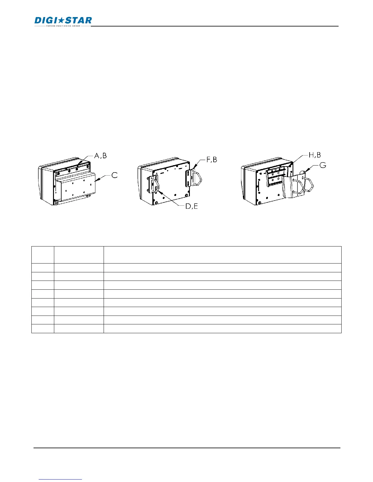
16.1 Indicator Mounting
For most applications the equipment manufacturer provides the necessary mounting system
and hardware, and mounts the Indicator for the End User.
Digi-Star provides a number of mounting options that allow the end user to customize the
location and placement of the Indicator. The following section provides a list of the optional
mounts.
In all cases the Digi-Star Indicator must be securely mounted to the equipment. Loose, or
unsupported, Indicators can be damaged.
KEY
PART
NUMBER
DESCRIPTION
A
404353
BRACKET-EZ3 PLASTIC RAIL *
B
403780
SCR-#10 X 5/8 FHSTS BLACK ZP
C
840459
SUPPORT-HAT BRACKET
D
405069
U-BOLT 1/4-20 X 3.25 ZP
E
405084
NUT-1/4-20 TOP LOCKING FLANGE
F
403770
BRACKET- WING MOUNT *
G
405124
PACK-WEDGE MOUNT BRACKET WITH U-BOLTS & FLANGE NUTS
H
405244
EZ3 WEDGE MOUNT
STD UNIVERSAL
MOUNT TALL
WING NUT
WEDGE MOUNT
Installation

Table of Contents

Related product manuals