NCH02 User’s ManualDigital Dream Motion Controller Page -19
Picture 4-5 Input Parameter Configuration (INPUT)
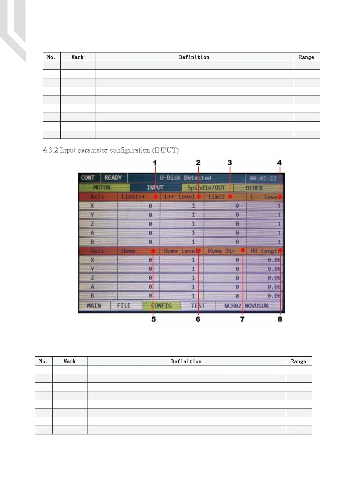
4.3.2 Input parameter configuration (INPUT)
1
3
4
5
6
7
8
9
2
No. Mark Definition Range
Stepsper 100-20000
50-20000
50-5000
10-200
0-100%
1/0
1/0
1/0
0-10
The number of pulses required for each 1mm feeding
The Max. Speed for Manually operation or the G-code file running.The unit is mm/min.
The Max. Acceleration for manual operation or G-code file running.The unit is mm/min
2
.
Z Axis Safety Height.The Unit is mm.
Backlash Speed
Backlash Enable,1=Enabe,0=disable.
Backlash Length,The unit is mm.
The Pulse Signal ELectric Level.0=Low,1=High
The Direction Signal ELectric Level.0=Low,1=High
Velocity
Accel
Safe-Z
BL SEPPD
Step Level
Dir Level
BL Enable
BL Length
1
3
4
5
6
7
8
2
No. Mark Definition Range
Limit++
L++ Level
Limit--
L-- Level
Home
Home Level
Home Dir
HKB Length
0-8
1/0
0-8
0-8
1/0
1/0
1/0
0-100
The Hard Limit at forward direction Pin setting.0=close the limit;1=IN1,2=IN2...8=IN8.
The Hard Limit at backward direction Pin setting.0=close the limit;1=IN1,2=IN2...8=IN8.
Active Level of forward direction limit.0=disable,1=enable
Active Level of backward direction limit.0=disable,1=enable
Home Pin Setting.0=Disable;1=IN1,2=IN2...8=IN8.
Back off distance after Home,the unit is mm
HOME direction.0=Backward,1=forward.
The HOME Signal ELectric Level.0=Low,1=High
The Picture 4-5 showed above it is the Input Parameter configuration page.At the chart below we explain
each column setting.By turning the rotary&push button,the user can select and edit the values and confirm.