Product Description
Use
The vacuum pump is intended for
–
the suction
of
–
air and other dry, non-aggressive, non-toxic and non-explosive
gases
Conveying media with a higher density than air leads to an increased
thermal and mechanical load on the vacuum pump and is permissible
only after prior consultation with Busch.
Permissible temperature range of the inlet gas: see “Oil”, “Ambient
temperature range”
In case the vacuum pump is equipped with a gas ballast (optional) wa
-
ter vapour within the gas flow can be tolerated within certain limits
(Ú Installation and Commissioning à Operating Notes à Conveying
Condensable Vapours). The conveyance of other vapours shall be
agreed upon with Busch.
The vacuum pump is intended for the placement in a non-potentially
explosive environment.
Version with float valve (j, 200) and oil return line:
The vacuum pump is thermally suitable for continuous operation.
Version with oil return valve (f, 280):
The vacuum pump is thermally suitable for continuous operation (ob
-
serve the notes with regard to the oil recirculation, Ú Product Descrip
-
tion à Oil Recirculation; Ú Installation and Commissioning
à Operating Notes à Oil Recirculation).
The vacuum pump is ultimate pressure proof.
Principle of Operation
The vacuum pump works on the rotating vane principle.
A circular rotor (s, 14) is positioned centrically on the shaft of the
vacuum pump. The shaft of the vacuum pump is driven by the drive
motor shaft by means of a flexible coupling (310).
The rotor (s, 14) rotates in an also circular, fixed cylinder (t, 1), the
centreline of which is offset from the centreline of the rotor such that
the rotor and the inner wall of the cylinder almost touch along a line.
Vanes (r, 22), sliding in slots in the rotor, separate the space between
the rotor and the cylinder into chambers. At any time gas is sucked in
and at almost any time ejected. Therefore the vacuum pump works al
-
most pulsation free.
In order to avoid the suction of solids, the vacuum pump is equipped
with a screen (261) in the suction connection.
In order to avoid reverse rotation after switching off, the vacuum
pump is equipped with a non-return valve (257).
Note: This valve shall not be used as a non-return valve or shut-off
valve to the vacuum system and is no reliable means to prevent suction
of oil into the vacuum system while the vacuum pump is shut down.
In case the vacuum pump is equipped with a gas ballast (optional):
Through the gas ballast valve (440) a small amount of ambient air is
sucked into the pump chamber and compressed together with the pro
-
cess gas. This counteracts the accumulation of condensates from the
process gas inside the vacuum pump (Ú Installation and Commis
-
sioning à Operation Notes).
The gas ballast line is equipped with a sinter metal filter.
RA 0025 - 0040 F Product Description
0870139077 / 051214 page 3
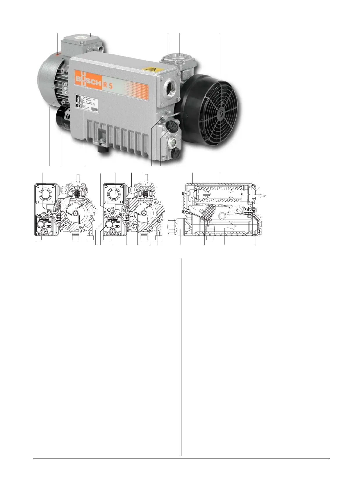
a b c d e
f g h i j c k d j l m n o p c
l m n q r s t h u v w
a Terminal box
b Directional arrow
c Gas discharge
d Suction connection
e Axial flow fan
f Oil return valve (version
with oil return valve only)
g Nameplate, drive motor
h Oil filter
i Nameplate, vacuum pump
j Float valve with oil return
line (version with float valve
and oil return line only)
k Eye bolt
l Oil fill plug
m Oil sight glass
n Oil drain plug
o Oil separator
p Exhaust filter
q Exhaust valve
r Vane
s Rotor
t Cylinder
u Demister
v Oil sump
w Service cover