Assessment
If
the reading on the filter pressure gauge is in the red field,
or
the drive motor draws too much current and/or the pump flow rate
has dropped,
then the exhaust filter (p, 122) is clogged and must be replaced.
Note: Exhaust filters cannot be cleaned successfully. Clogged exhaust
filters must be replaced with new ones.
If
the filter pressure gauge indicates a lower pressure than usual,
or
the drive motor draws less current than usual,
then the exhaust filter (p, 122) is broken through and must be
replaced.
If the discharged gas contains oil,
the exhaust filter (p, 122) can either be clogged or broken through
and, if applicable, must be replaced.
Change of the Exhaust Filter
DANGER_age32
In case the vacuum pump conveyed gas that was contaminated
with harmful foreign material the exhaust filter will be contami
-
nated with harmful material.
Danger to health during the changing of the contaminated exhaust
filter.
Danger to the environment.
Wear personal protective equipment during the changing of the
contaminated exhaust filter.
Used exhaust filters are special waste and must be disposed of
separately in compliance with applicable regulations.
CAUTION_a1
The filter spring (125) can fly out of the exhaust port during re
-
moval or insertion.
Risk of eye injury.
Eye protection goggles must be worn while handling filter springs
(125).
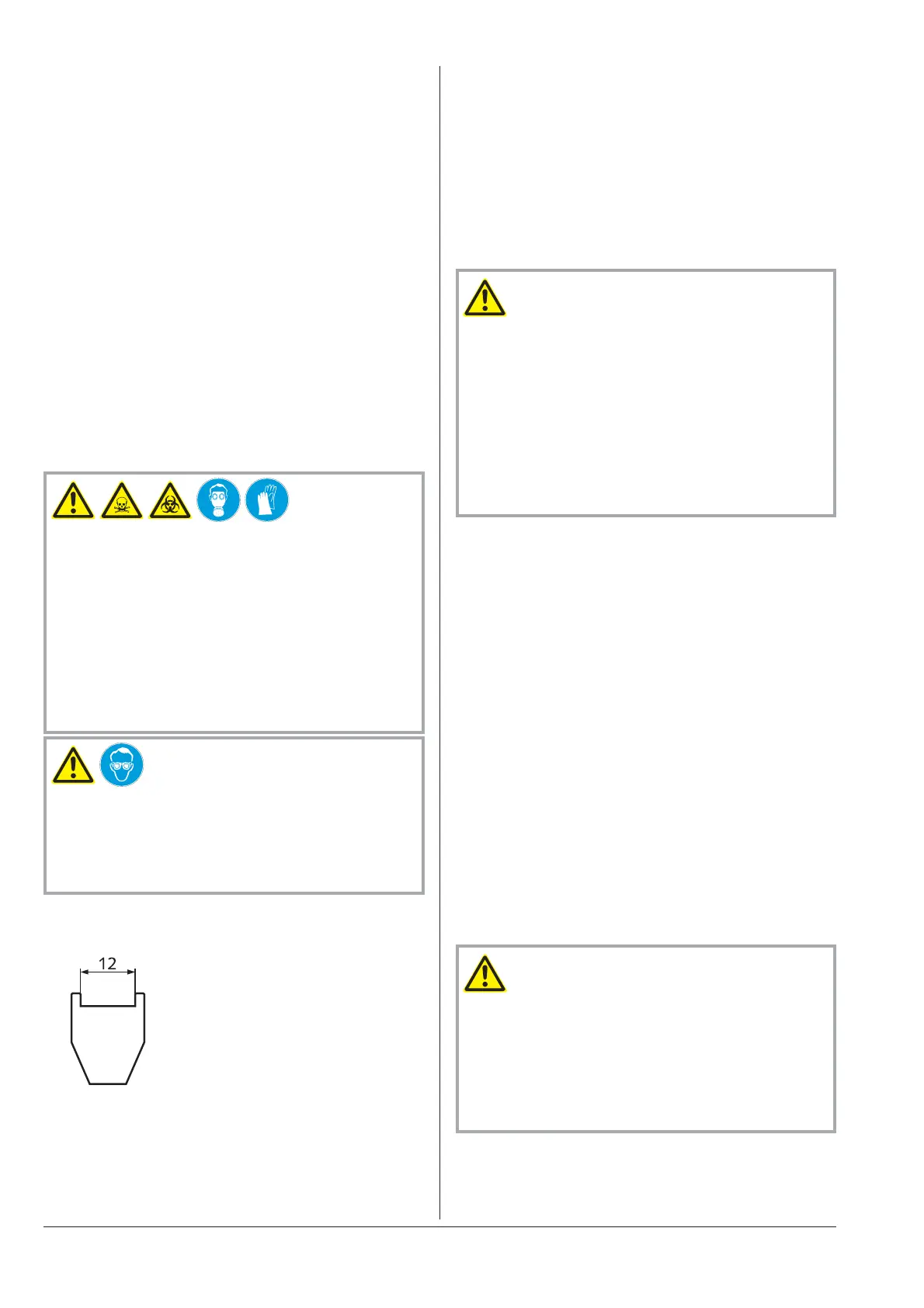
Note: In order to facilitate the removal and insertion of filter springs
(125) it is recommend to make a special tool:
◆
Make a fork acc. to the sketch from
approx. 2 mm steel plate
◆
Weld the bottom end of the fork to
the tip of a medium size slotted head
screw driver
Removing the Exhaust Filter
●
Make sure that the vacuum pump is shut down and locked against
inadvertent start up
●
Prior to disconnecting pipes/lines make sure that the connected
pipes/lines are vented to atmospheric pressure
●
Remove the discharge line, if necessary
●
Remove the exhaust cover (c, 155) from the oil separator (o, 75)
●
Loosen the screw in the centre of the exhaust filter retaining spring
(125), but do not remove it at this time
●
With the aid of the special tool press the exhaust filter retaining
spring (125) out of the indent and rotate it
●
Remove the exhaust filter retaining spring (125) from the oil sepa
-
rator
●
Pull the exhaust filter (p, 122) out of the oil separator (o, 75)
Inserting the Exhaust Filter
CAUTION_a
The non-OEM spares market offers exhaust filters that are geomet
-
rically compatible with Busch-vacuum pumps, but do not feature
the high retention capacity of genuine Busch-exhaust filters and de
-
teriorate the service life and the efficiency of the vacuum pump due
to their increased back pressure.
Increased risk of damage to health.
Adverse effect on efficiency and service life.
In order to keep the emission on the lowest possible level and to
preserve efficiency and service life only genuine Busch-exhaust fil
-
ters shall be used.
●
Make sure that the new exhaust filter (p, 122) is equipped with a
new o-ring
●
Insert the exhaust filter (p, 122) such that its port is properly
seated in its receptacle in the oil separator (o, 75)
● Make sure that the tip of the screw in the centre of the exhaust fil-
ter retaining spring (125) protrudes the retaining spring by about
2 - 5 revolutions
● With the aid of the special tool insert the exhaust filter retaining
spring (125) such that its ends are secured in their receptacles in
the oil separator (o, 75) by the protrusions and that the tip of the
screw snaps into the indent of the exhaust filter (p, 122)
● Tighten the screw in the exhaust filter retaining spring (125) such
that the screw head touches the spring steel sheet
●
Make sure that the seal (141) under the exhaust cover (c, 155) is
clean and undamaged, if necessary replace with a new seal (141)
●
Mount the exhaust cover (c, 155) together with the seal (141), hex
head screws (146) and lock washers on the oil separator (o, 75)
●
If necessary connect the discharge line
Note: During operation the exhaust filter gets saturated with oil. It is
therefore normal that the oil level will drop slightly after replacement
of the exhaust filter.
Overhaul
CAUTION_a
In order to achieve best efficiency and a long life the vacuum pump
was assembled and adjusted with precisely defined tolerances.
This adjustment will be lost during dismantling of the vacuum
pump.
It is therefore strictly recommended that any dismantling of the
vacuum pump that is beyond of what is described in this manual
shall be done by Busch service.
Overhaul RA 0025 - 0040 F
page 12 0870139077 / 051214