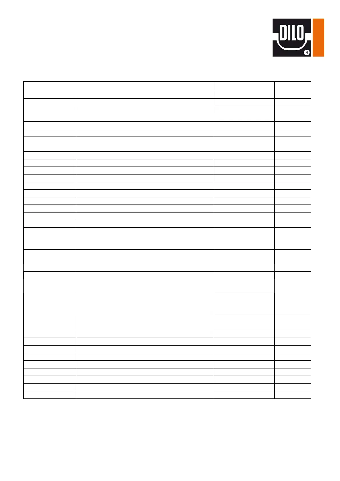
Parts list for circuit diagram
www.dilo-gmbh.com | 1001-S01.bae
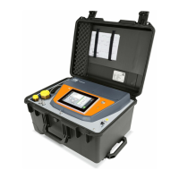
Gas handling unit
Pos. Designation Article no. Piece
A01 3.6" Display 05-1657-R100 1
A02 5.7" colour Touch panel 05-1657-R103 1
B01 Phase sequence relay 05-1456-R001 1
B11 Thermistor control device 230V 05-0228-R006 1
F01 1 pole cut-out B6 05-0725-R003 1
F02 Discharger 230V 05-1509-R001 1
F03 1 pole cut-out
Power supply 3x208-240V: B6A
05-0725-R003
1
F11 1 pole Z1 cut-out 05-0725-R052 1
K01 SPS S7-1214C 14DE,10RA,2AE 05-1657-R003 1
K02 Extension module 8RA 05-1657-R021 1
K03 Extension module 4AE 05-1657-R031 1
K04 Extension module 4AE 05-1657-R031 1
K05 Communication module CM241 05-1657-R041 1
K06 Ethernet- switch 05-1587-R002 1
K51 Microprocessor controller 05-0701-R003 1
Q01 Reversing switch 05-0727-R007 1
Q02 Motor protection circuit breaker PKZM0-2,5 05-0891-R007 1
Q11 Motor starter basic device 05-1592-R002 1
Motor starter control device 05-1592-R016 1
Motor starter auxiliary switch 05-1592-R021 1
Q21 Motor starter basic device 05-1592-R001 1
Motor starter device 05-1592-R014 1
Motor starter auxiliary switch 05-1592-R021 1
Q31 Motor starter basic device 05-1592-R001 1
Motor starter control device 05-1592-R014 1
Motor starter auxiliary switch 05-1592-R021 1
Q51 Motor starter basic device 12A 05-1592-R001 1
Motor starter control device 05-1592-R016
Motor starter auxiliary switch 05-1592-R021 1
S01 Emergency Off key 1Ö
Contact element 1Ö
K101R31
05-0736-R102
1
1
S02 BCD switch, T0-4-15602/E 05-0728-R005 1
S03, S05 Double key 24V 1S 1Ö K101R01 2
S04 1 pole snap action switch 05-0467-R001
T01 Universal transformer, WA-U 630 05-0747-R020 1
T02 Power supply unit 24VDC/0,6A 05-1461-R101 1
T05 Operator display WE100-2 05-1820-R002 1
X01 Coupling 05-0751-R009 1
X02 Power plug 05-0752-R009 1
X03 Built-in socket; 1461-050 05-0753-R004 1