Dry-running compressor | TM 5.0 B
www.dilo-gmbh.com | C 1610-10 | Page 13 / 18
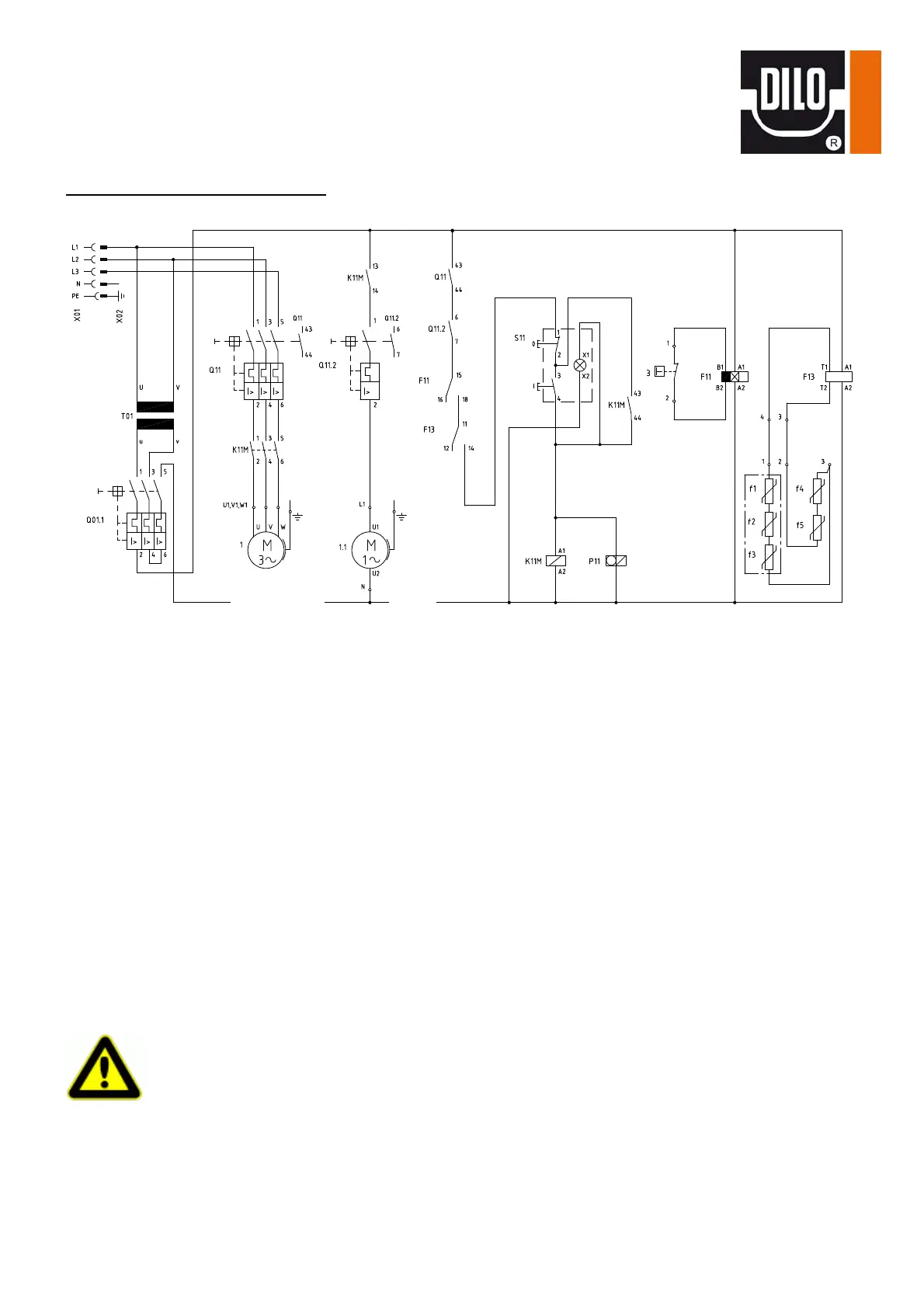
Circuit diagram (wiring example):
f1-f3 Lead probe (in the motor winding of the compressor)
f4/f5 Lead probe (in the cylinder caps of the compressor)
F11 Protective contact relay
F13 Thermistor-machinery protection
K11M Motor contactor
P11 Working hours counters
Q01.1/Q11/Q11.2 Motor protective circuit breaker
S11 On/Off button with indicator light
T01 Transformer
X01 Coupling
X02 Power plug
3 Contact gauge (the contact gauge must be connected to the output side of the
compressor)
SF
6
-gas connection
Check that connecting hoses are connected and tightened.
Check whether the suction pressure is limited to its max. value by a pressure reducer.
Verification of the safety equipment
Check whether the red pointer of the contact gauge (or pressure switch) that controls the
output pressure of the compressor which is adjusted not higher
than the max. admissible pressure of the compressor (pe 50 bar)!
compressor fan
Danger