12
© 2005 directed electronics, inc.
HH11//33 WWHHIITTEE//BBLLUUEE nnoo ffuunnccttiioonn..
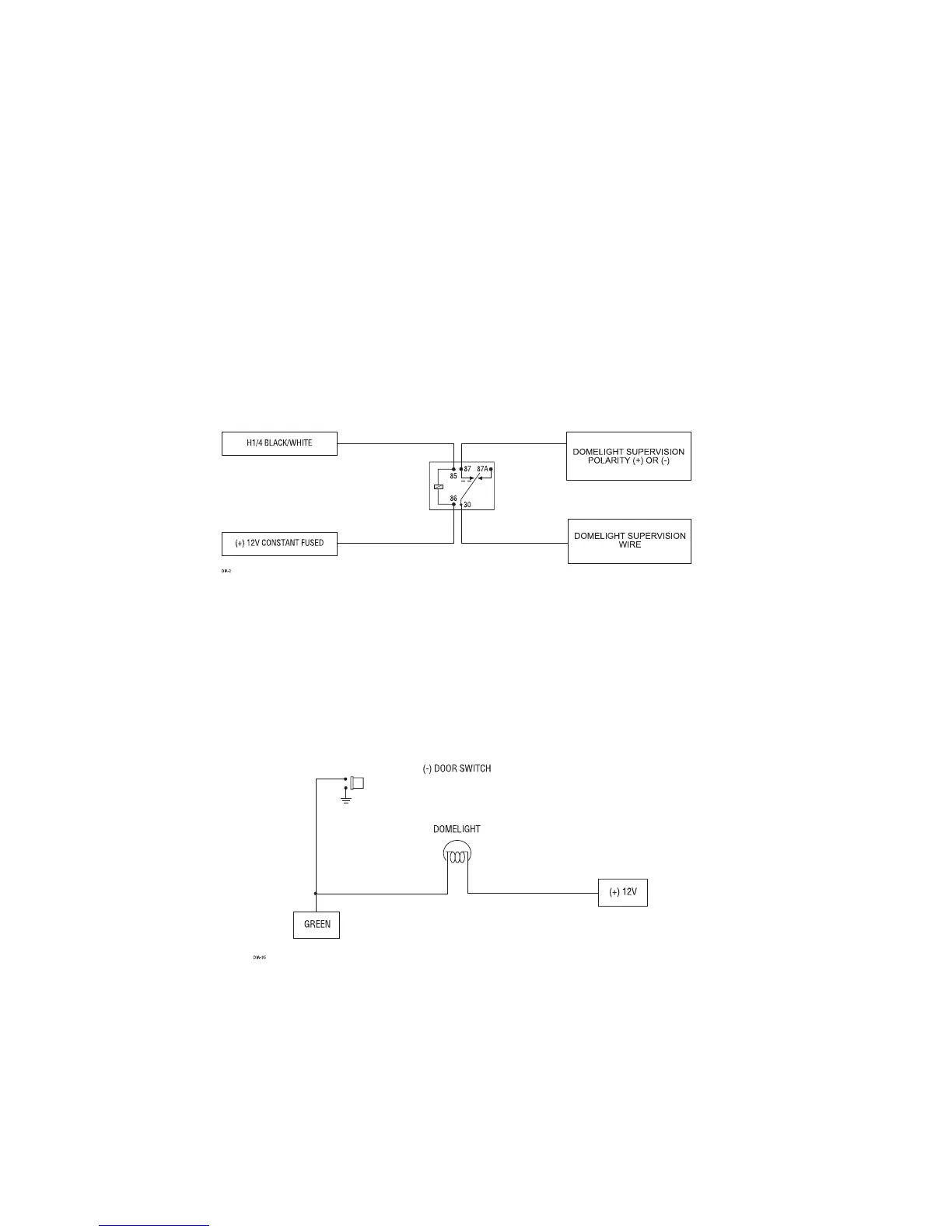
HH11//44 BBLLAACCKK//WWHHIITTEE ((--)) 220000 mmAA ddoommeelliigghhtt--ssuuppeerrvviissiioonn oouuttppuutt::
Connect this wire to
the optional domelight supervision relay.
IIMMPPOORRTTAANNTT!!
This output is only intended to drive a relay. It cannot be connected
directly to the domelight circuit, as the output cannot support the current draw of one
or more bulbs.
HH11//55 GGRREEEENN ((--)) ddoooorr ttrriiggggeerr iinnppuutt
: Most vehicles use negative door trigger circuits.
Connect the green wire to a wire which shows ground when any door is opened. In
vehicles with factory delays on the domelight circuit, there is usually a wire that is
unaffected by the delay circuitry.