© 2005 directed electronics, inc.
15
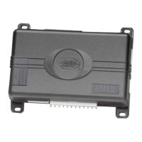
auxiliary harness wire connection guide
auxiliary harness wiring diagram
___
___
___
___
___
___
___
auxiliary harness wiring guide
HH22//11 BBRROOWWNN ((--)) hhoorrnn hhoonnkk oouuttppuutt::
This wire supplies a 200 mA (-) output that can
be used to honk the vehicle’s horn. It provides a pulsed output when the security sys-
tem is armed/disarmed and in the triggered sequence or in panic mode. In most vehi-
cle’s with (-) horn circuits this wire can control the vehicle’s horn without adding a
relay. If the vehicle has a (+) horn circuit, an optional relay must be used to interface
with the vehicle’s horn circuit.
IIMMPPOORRTTAANNTT!!
Never use this wire to drive anything but a relay or a low-current input!
This transistorized output can only supply (-) 200 mA, and connecting directly to a sole-
noid, motor, or other high-current device will cause the module to fail.
HH22//22 GGRREEEENN ffoorr aarrmm iinnppuutt::
Connect this GREEN wire to a wire that changes state when
the doors are locked using the factory keyless entry transmitter. This wire can accept a
positive (+) or negative (-) input. The vehicle’s power door lock motor wire is ideal.
HH22//33 RREEDD ddiissaarrmm ddeeffeeaatt iinnppuutt::
This wire is used to prevent the interior door lock
switches from disarming the system. To determine the best location to interface this
wire, first test the operation of the remote keyless entry system. When unlocking the
doors with the factory remote transmitter, does the driver’s door unlock first? Most
YELLOW/BLACK Light Flash Monitor Input
VIOLET/BLACK No Function
GRAY (+) Trunk Release/Sensor Shunt Input
BLUE Disarm Input
RED Disarm Defeat Input
GREEN Arm Input
BROWN (-) Horn Honk Output
H2/1
H2/2
H2/3
H2/4
H2/5
H2/6
H2/7