48
DS4+ FORD6
© 2017-12-13 Directed. All rights reserved.
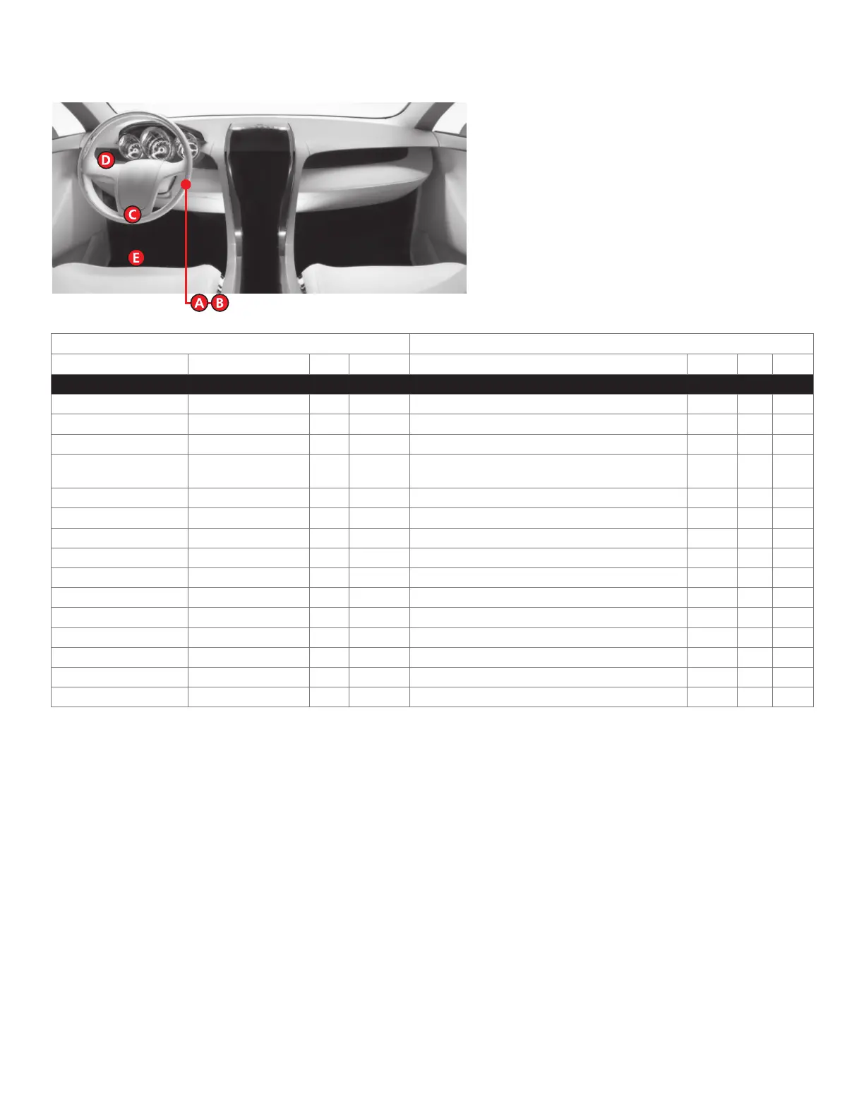
Vehicle wiring reference chart
This section provides vehicle wiring information to guide you through the various stages of your installation. Refer to
www.directechs.com for additional information.
Wire Information Connector Information
Function Color Pin Polarity Location Color Pins Ref.
Ford F150 2008
RX Gray/Orange 4 Data (PATS) connector. Green 4 A
TX White/Lt. Green 3 Data (PATS) connector. Green 4 A
12V Lt. Green/Violet 4 (+) Ignition switch. Black 7 B
Starter Red/Lt. Blue or Blue/
White
7 (+) Ignition switch. Black 7 B
Ignition Dk. Blue/Lt. Green 1 (+) Ignition switch. Black 7 B
Accessory Black/ Lt. Green 6 (+) Ignition switch. Black 7 B
Parking Lights Brown 5 (+) Headlight switch. Gray 10 D
HS CAN High White/Lt. Green 6 Data OBDII. Black 16 C
HS CAN Low Pink/Lt. Green 14 Data OBDII. Black 16 C
Driver Door Trigger Black/Yellow N/A (-) Driver kick panel harness to rear. N/A N/A E
Lock Pink/Yellow N/A (-) Driver kick panel harness to rear. N/A N/A E
Unlock Pink/Lt. Green N/A (-) Driver kick panel harness to rear. N/A N/A E
MS CAN High N/A N/A N/A N/A N/A N/A N/A
MS CAN Low N/A N/A N/A N/A N/A N/A N/A
Tach NOT Red N/A (AC) Any fuel injector. N/A N/A N/A
 Loading...