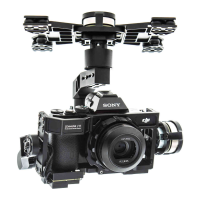
Zenmuse Z15-A7
User Manual
©
2015 DJI. All Rights Reserved.
23
1. Prepare one 14-channel TX/RC receiver for the aircraft and gimbal control. Above is an example of the
wiring conguration.
2. Setup the Aileron, Elevator, Throttle, and Rudder channels on your TX for aircraft roll, elevator, throttle, and
rudder control. Also, connect the TX’s AUX2 for aircraft control modes (Please refer to your Flight Control
System’s user manual).
3. Choose three 3-position switches to use for the gimbal Roll, Tilt, and Pan rotation control. The center
position of each switch is 0 velocity, and the end point positions are maximum velocity.
4. Choose one 3-position switch/channel as the gimbal’s Working Modes switch (MODE).
5. Choose one 2-position switch/channel as the camera shutter control switch (SHUT).
6. Connect the receiver to the GCU and Flight Control System correctly.
2-Pilot Solution
OR
OR
S-Bus
GCUGCU
ROLL
TILT
PAN
MODE
SHUT
AUX1
AUX2
AUX3
Gimbal Control Unit(GCU)
Transmitter A
Gimbal Control
Flight Controller
RC Receiver B
RC Receiver
(JR)
8 Channels
RC Receiver
(JR)
8 Channels
S-Bus
Transmitter B
OR
OR
DJI WooKong-M Flight Controller
RC Receiver
(Futaba/Hitec)
8 Channels
RC Receiver
(Futaba/Hitec)
8 Channels
S-BUS Receiver
(Futaba)
S-BUS Receiver
(Futaba)
2-Position Switch
2-Position Switch
3-Position Switch
2-Position Switch
2-Position Switch
2-Position Switch
3-Position Switch
2-Position Switch
14V
52V
A7
HD
-
Two transmitters and two receivers are required.
Transmitter A and receiver A are used to control the gimbal.
Transmitter B and receiver B are used to control the aircraft.
Make the connections as shown in the diagram below:
Appendix
Please refer to the
GCU Wiring
section for more details.

 Loading...