©
2015 DJI. All Rights Reserved.
7
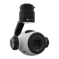
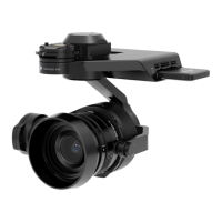
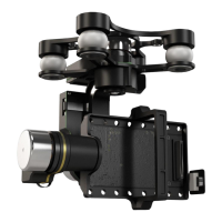
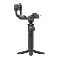
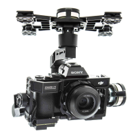
Z15-A7 Diagram
To avoid motor damage, ensure there is nothing blocking the rotation of the servo drive modules.
Clear obstacles or immediately cut off the power if any blockage occurs.
The servo drive modules have two motor command input ports and one private encoder port.
The HDMI-HD/AV module converts HDMI to HD (or AV) using a cable connected to the camera
HDMI port; it also transforms the TX signal to an infrared remote control module for shutter control
and video recording.
Motor lnput Port to
G6 Port of GCU
Servo Drive Module 1
Damping Unit
Receiver Mounting
Board
Servo Drive Module 3
IMU Module
Camera Mounting Holes
Gimbal LED
Indicator
HDMI-HD/AV Module
HD/AV Switch
HDMI Cable
Camera Mounting
Position
Tilt +50°/-140°
Arrow represents
the lens direction
Pan
±360°
Roll ±40°
Servo Drive
Module 2
9-Pin Port to G9
Port of GCU
Z15-A7 Diagram
 Loading...