8860 Installation and Programming Guide | Digital Monitoring Products 5
INSTALL THE KEYPAD
1
Run Wire
Run wire from the power source to the keypad mounting location. See Keypad Bus Wiring Specifications section
on page 16 for maximum wire runs.
2
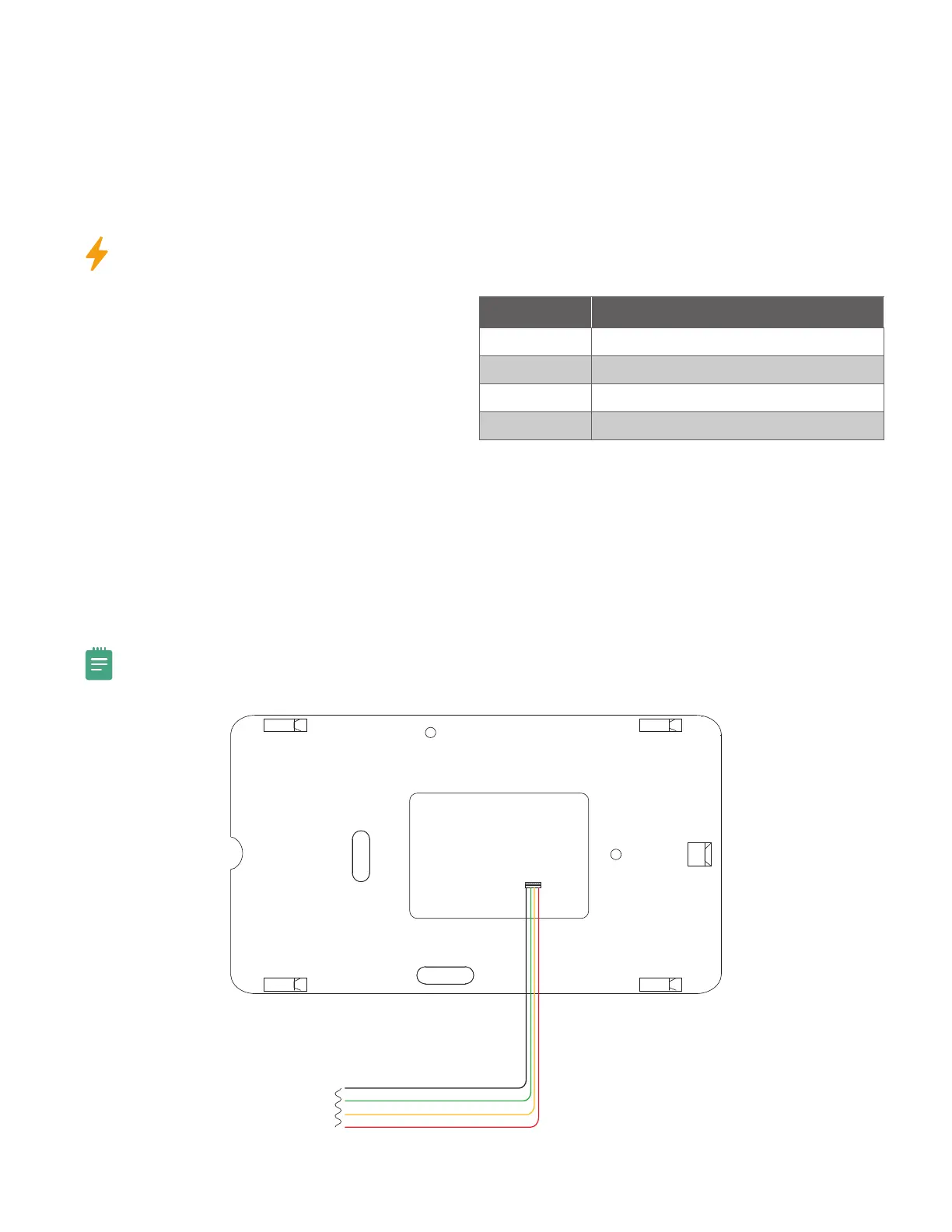
Wire the Keypad
Caution: Disconnect all power before wiring. Failure to do so may result in equipment damage or injury.
Observe polarity when making power connections.
Keypad Bus Connection
1. Connect the red wire to panel terminal 7.
2. Connect the yellow wire to panel terminal 8.
3. Connect the green wire to panel terminal 9.
4. Connect the black wire to panel terminal 10.
Network (Wi-Fi) Connection
1. Plug the harness into the back of the keypad with the black wire at B and the red wire at R.
2. Connect the black wire to the power supply’s negative terminal.
3. Connect the red wire to the power supply’s positive terminal.
4. Plug the power supply into an unswitched outlet.
5. Refer to Device Type in the Programming the Panel section of this document for programming instructions.
Note: DMP recommends performing system power calculations before installing more than one device on the
keypad bus.
WIRE COLOR PURPOSE
Black Ground from Panel*
Green Receive Data from Panel*
Yellow Send Data from Panel*
Red Power from Panel or Auxiliary Power Source*
*Required connections
Black - Ground
Green - Receive Data
To Panel
Keypad Bus
Yellow - Send Data
Red - Power
Keypad
Back
Figure 2: Keypad Wiring