23
SAW BAND PREPARATION (Continued....)
6. Maneuver the drive bandwheel end loop of the saw
band outward and to the right while maneuvering
the idler bandwheel end loop between the idler
bandwheel and the left saw band guard. Then: (a)
Manipulate the top part of the saw band out between
the right saw band arm and the band brush deector
shield; (b) Recoil the saw band and dispose of it
immediately.
Saw Band Installation
Always use extreme care when handling saw
bands. DO NOT attempt to change saw bands
while the band drive motor is running.
1. Carefully follow all "Saw Band Removal" procedures.
Then: (a) Use the Flushing Hose to clean areas
around the saw guides and inserts, plus the drive
and idler bandwheels.
2. Slip the saw band under both saw guide arms by
following the the reverse procedure of step 4 in the
"Saw Band Removal" section. Then: (a) Position the
saw band around the drive and idler bandwheels.
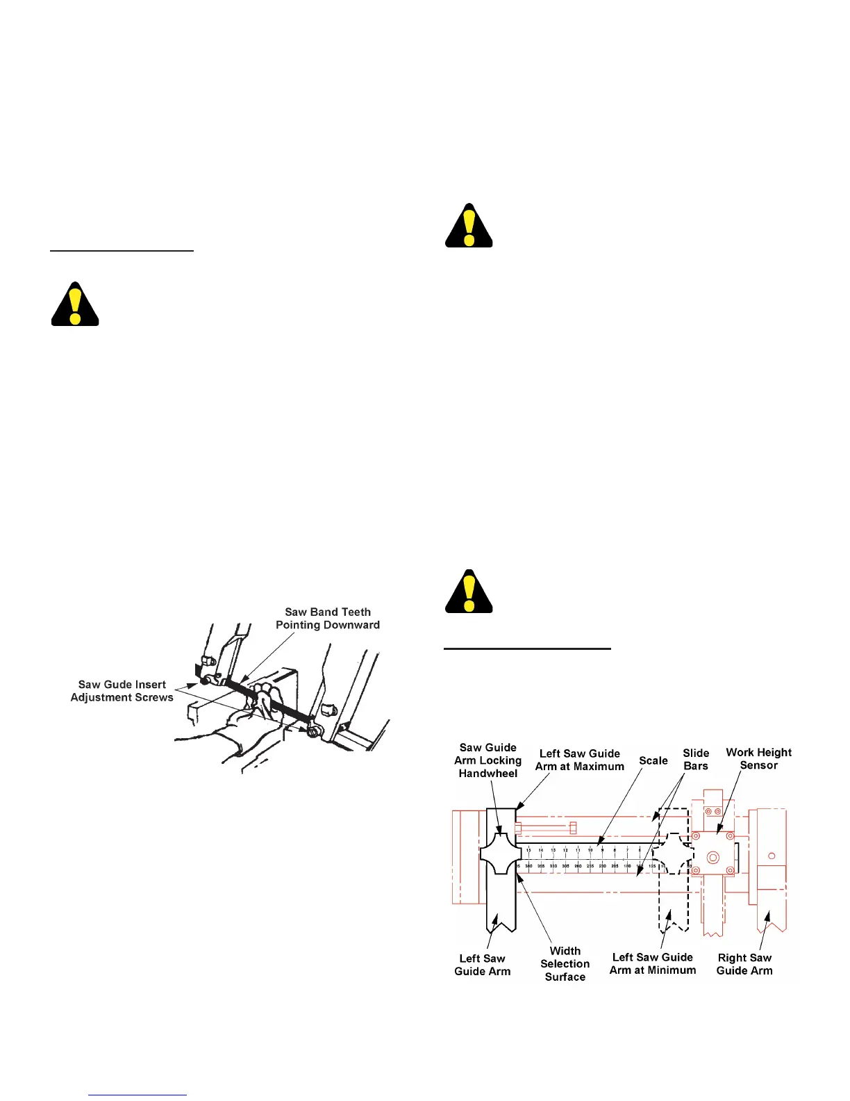
3. Slip the top portion of the saw band loop into the
top channel guards. Then: (a) Grasp the saw band
portion between the saw guide arms and twist it so
the blade teeth are pointing downward; (b) Slip this
twisted saw band portion up and between the saw
guide inserts.
Placing the Saw Band Between the Saw Guide Inserts.
4. Check the saw band’s position around both
bandwheels (its back edge must rest against each
wheel’s rear ange). When satised that saw band
positioning is correct: (a) Turn the Band Tension
selector to “ON”; (b) Move the left saw guide arm
to the desired position; (c) Tighten both saw guide
insert adjustment screws.
5. Reposition the band brush and tighten the clamp
screw (brush bristles should clean the blade
teeth gullets, but not contact the bottom of the
gullets). Then: (a) Close both bandwheel doors; (b)
Jog the band drive motor; (c) Open each bandwheel
door to make certain that the saw band is against
the bandwheel anges.
LEFT SAW GUIDE ARM ADJUSTMENTS
The right saw guide arm cannot be adjusted.
1. The left saw guide arm moves along the slide bar to
accomodate various stock widths (the arm should
be positioned as close as possible to the clamped
stock).
2. Stock width settings are depicted by two (2) slide
bar scales: (a) Use the upper scale for rectangle
stock; (b) Use the lower scale for round and square
stock measurements.
3. To adjust the left saw guide arm according to stock
width, the operator loosens the left insert adjustment
screw and the guide arm locking handwheel. Next:
(a) Line up the left saw guide arm's right edge with
the proper inscribed scale line; (b) Secure the saw
guide arm in the chosen location by tightening the
guide arm handwheel; (c) Tighten the left insert
adjustment screw.
DO NOT hammer the lobes of the locking
handwheel. Hand tightening is adequate to
lock the left saw guide arm in place.
Using the Slide Bar Scale
1. Use the lower portion of the slide bar scale to
position the left saw guide arm for all stock sizes
and gurations except the maximum height
rectangularconguration.
Slide Bar Scale.