34
MAINTENANCE
REPLACING SAW GUIDE AND BACK-UP
INSERTS
These instructions can be used to replace
the saw guide and back-up inserts on both left
and right saw guide arms.
Be sure the band drive motor is not running
when replacing saw guide and back-up
inserts.
1. Loosen the insert adjustment screw on each saw
guide arm. Then: (a) Remove the left saw band
guard (if necessary) and saw band; (b) Remove
the adjustment screw being very careful not to
drop or lose the front insert when it falls from
the assembly; (c) Loosen the at head screw and
remove the rear insert.
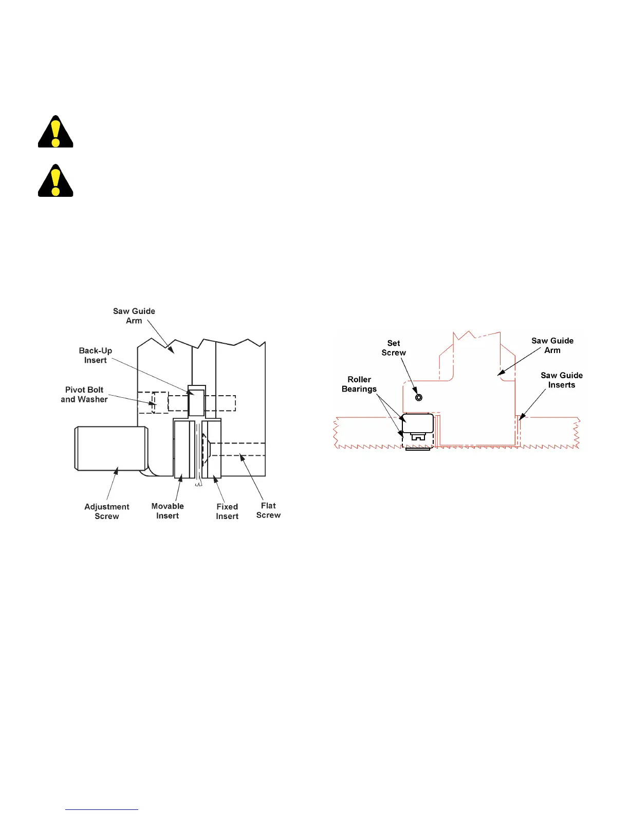
Typical Saw Guide Assembly (Both Arms).
2. Thoroughly clean the saw guide arm and inserts
area. Then: (a) Reverse the carbide back-up insert
(if worn); (b) Replace the rubber back-up insert if
it has deteriorated (this will help prevent coolant
leakage).
3. Install the new inserts. Then: (a) Thread the adjusting
screw inward part way; (b) Place the saw band
between the inserts; (c) Tighten the adjustment
screw; (d) Replace the left saw band guard (if
removed).
ADJUST OR REPLACE SAW BAND LEAD-IN/
EXIT ROLLERS
1. To adjust and position the xed spindles/rollers: (a)
Raise the saw head until the saw band is above the
front movable vise jaw; (b) Shut the machine and
disconnect switch off; (c) Move the left saw guide
arm to the closest approach to the right saw guide
arm.
2. Insert a straightedge gage and clamp the inserts in.
Position the bearing blocks so that the xed splindle
rollers bear evenly on the straightedge gage.
3. Loosen the set screw above the roller bearing and
pull out the roller bearings. Then: (a) Remove the
screw or retaining ring holding the bearing in place;
(b) Remove old bearing and replace with new one;
(c) Reinstall the screw or retaining ring; (d) Tighten
the set screw.
Lead-In/Exit Roller Bearings.
BAND DRIVE BELT REPLACEMENT
1. Turn one (1) disconnect switch to "OFF". Then:
(a) Remove the band drive assembly cover; (b)
Remove the broken drive belt.
2. Position the new drive belt over the drive pulley
sheaves. Then: (a) Adjust the motor base plate
slack take-up.
3. Turn the disconnect switch to "ON". Then: (a)
Check the operation of the new drive belt ; (b) If the
operation is satisfactory, turn the band drive motor
off; (c) Replace the assembly cover.
HYDRAULIC SYSTEM
1. Keep the reservoir lled at all times. Capacity is 10
gallons (37.5 liters). Check the reservoir oil level
daily by referring to the sight gauge.