36
MACHINE ALIGNMENT
1. Misalignment of the machine’s saw guide arms, slide
bar, saw band, pivot points, transmissions, etc., will
cause inaccurate sawing.
DO NOT attempt any alignment procedures
not covered by this manual. Contact a
DoALL service representative in such cases
becausespecialxturesandtechniquesmay
be required.
BAND BRUSH
1. The band chip brush will wear and lose steel bristles
over time. Check often to be sure the bristles are
removing metal chips from the blade tooth gullets,
but are not touching the bottom of the gullets.
2. Move the brush closer to the blade as normal wear
occurs. Replace the brushes when necessary.
BAND TENSION MEASUREMENT
1. Band tension is factory set.
• Band tension measurement can be made with the
machine’s hydraulics running and by using the Band
Tension selector and a DoALL Tensigage.
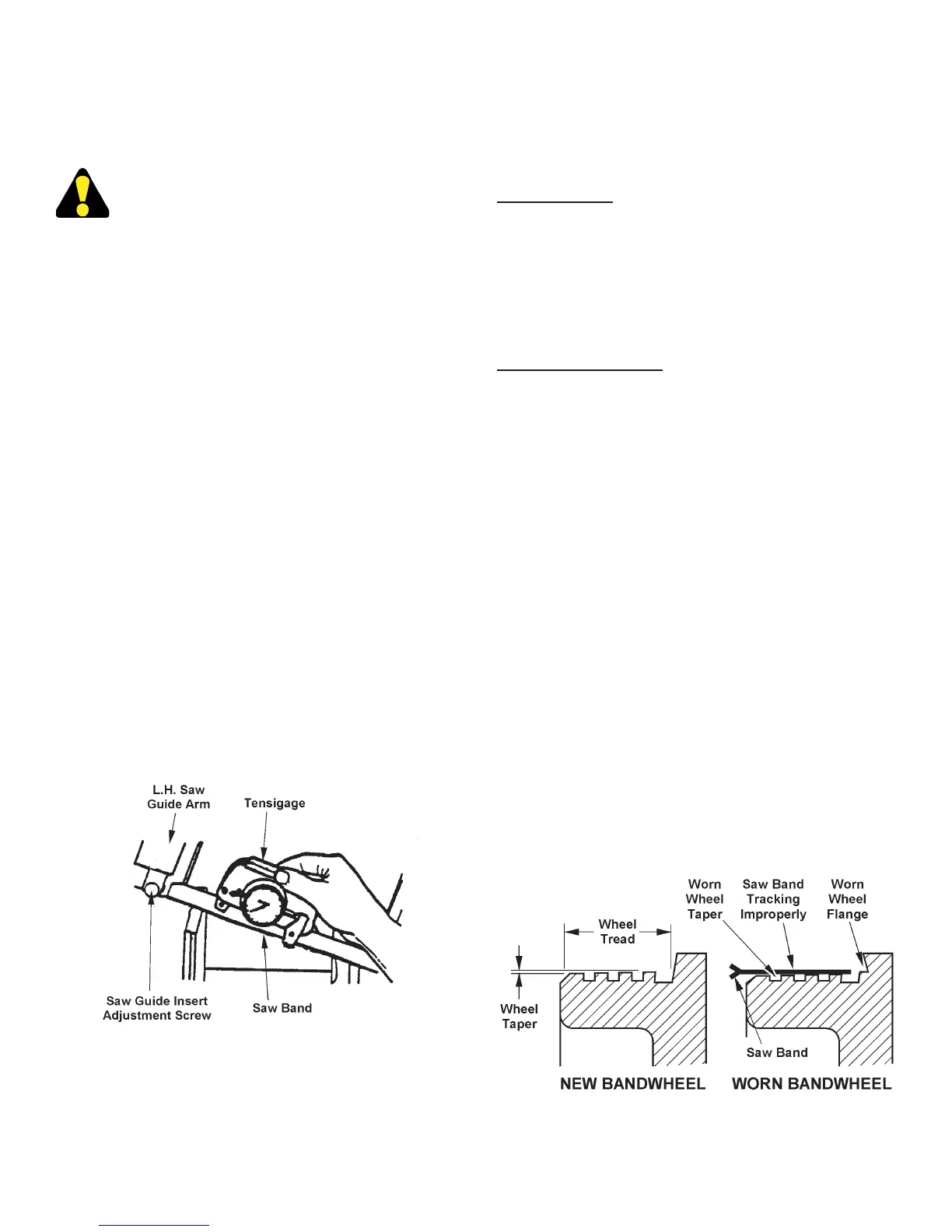
2. Tension may be checked "reading up" or "reading
down". To "read up": (a) Fix the Tensigage to a
slack saw band; (b) Apply tension. To "read down":
(a) Fix the Tensigage to a tensioned saw band; (b)
Relax tension.
3. A DoALL Tensigage reading of 3.8 to 4.0 indicates
correct saw band tension.
Using a Tensigage to Measure Band Tension.
WEAR PLATE REPLACEMENT
1. The removeable vise jaw and vise guide bars must
be replaced before excessive wear causes the
mounting screw heads to become damaged and
makes removal difcult.
Vise Jaw Plates
1. The machine has eight (8) vise jaw wear plates: four
(4) on the front vise jaws and four (4) on the index
vise jaws. All wear plates are mounted with low-head
screws. Be sure the vise jaws are separated and
the machine turned off before trying to replace
the wear plates.
Front Vise Guide Rails
1. Each of the two (2) front vise guide rails has seven
(7) mounting screws which must be removed.
Replacement requires: (a) Removing the mounting
screws; (b) Pulling the guide rails toward the left.
BAND DRIVE TRANSMISSION
1. Transmission replacement, repair, adjustment or
alignment should be performed only by a DoALL
service representative.
BANDWHEELS
1. Occasionally check each bandwheel’s back-up
ange and wheel tread for wear. Saw bands will
not track properly if the taper is worn from the wheel
tread.
2. Replace the entire bandwheel if the rim becomes
badly worn.
3. Ideally, the saw band should be tracking on both
wheels so that the back edge will just lightly contact
the wheel anges, or is not more than 0.005 inch
(0.127 mm) away from the anges.
Bandwheel Flange and Tread.