26
COOLANT SYSTEM (Continued....)
Sensing Arm Operation When the Saw Head Lowers
1. The saw head lowers at the rapid approach rate
until stock is contacted by the sensing arm. A
feed approach rate is then established and cutting
begins.
2. Sensing arm contact with the stock is maintained
throughout the cut. After a cut has been nished:
(a) The head down proximity switch (2 PRS or 2
LS) is actuated; (b) The saw head raises.
MINIMUM BAR END/SPLIT FRONT VISE
1. When the indexing vise is completely forward, both
of its vise jaws extend toward the front vise jaws.
This extension, together with the nesting design of
the vises, permits automatic indexing of stock until
a small butt end remains.
2. The minimum butt end length of stock that can be
indexed is three (3) inches (76.2 mm). If the stock
is shorter, it will not be stable in the index vise.
VERTICAL GUIDE ROLLER
1. This roller mounts to the tail block at the rear of the
feed table and provides one (1) laterally adjustable
vertical roller.
2. The vertical roller is xed in relation to the xed jaw
face. When the vertical roller is not needed, it can
be removed.
HYDRAULIC SYSTEM
1. The hydraulic and band drive systems operate
independently. This allows the operator to perform
the following tasks while the band drive motor is
not running: (a) Change saw bands; (b) Raise or
lower the sawing head; (c) Clamp or unclamp the
vises; (d) Position stock manually.
2. The machine's hydraulic reservoir has a 10 gallon
(37.8 liter) capacity. Refer to the Lubrication section
of this manual for recommended oils.
COOLANT SYSTEM
Coolant Selection
1. The main cause of tooth failure during band
machining is excessive heat build-up. Using the
proper cutting uid reduces the heat generated
during operation. It also helps the machine take
full advantage of its high-speed steel saw bands.
Literature describing these and other coolant
types is available from a DoALL sales
representative.
Coolant Application
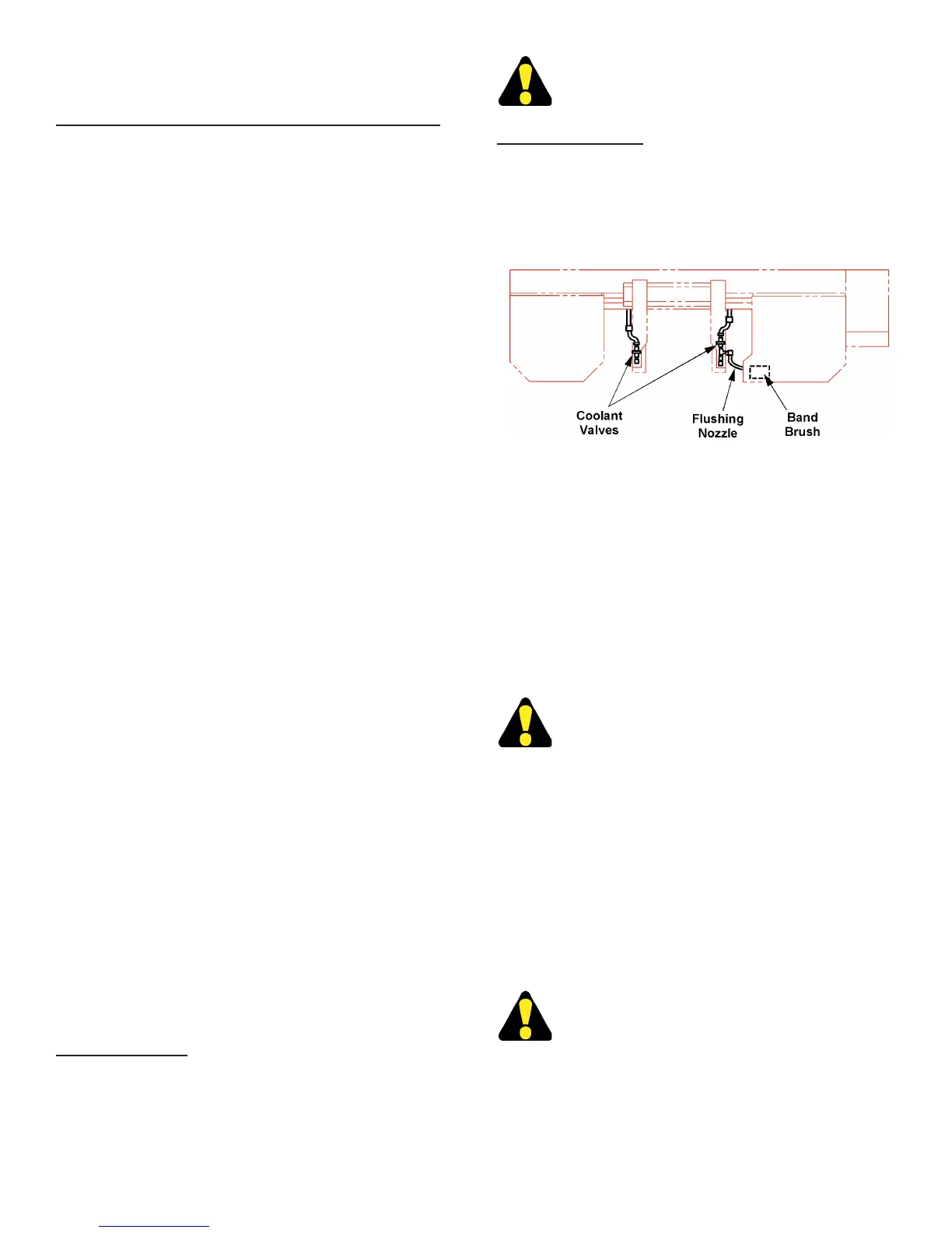
1. Coolant is applied as follows during sawing:
• To the saw band and cutting area through the saw
guide inserts. Flow is regulated by a valve on each
saw guide arm.
Coolant Application Points.
• To the band brush cleaning area through a ushing
nozzle. Flow from this point is controlled by a needle
valve. If the valve orice becomes clogged, clean
it with a wire or small pin.
2. Coolant ow is started by: (a) Pushing the Hydraulic
Start button; (b) Turning the Coolant selector to
"ON" or "BAND ON"; (c) Turning the coolant valve
on each saw guide arm counterclockwise until
uid completely shrouds the saw band.
DONOTstartcuttinguntilcoolantisowing
adequately. Dry cutting will greatly reduce
blade life.
3. Check the coolant reservoir level if ow is stopped
or reduced. Reservoir capacity is 20 gallons (75.7
liters). A coolant level sight gauge is located on the
machine’s lower right side of the base.
CHIP REMOVAL
1. Metal chips should be removed from the work area as
soon as possible. They can be washed or scraped
into the right front pan opening, or scooped out with
the supplied shovel-rake.
DO NOT shovel or rake chips while the saw
band is running.
AUTOMATIC HEAD ELEVATION and SENSING
ARM (Auto Mode Only) (Continued....)