28
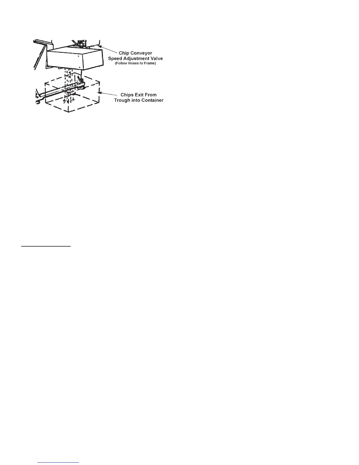
Chip Conveyor Discharges Material at Machine's Right Side.
3. A valve located on the right side near the band
drive enclosure allows the chip auger motor to be
adjusted for faster or slower operation.
IDLER WHEEL MOTION DETECTOR
1. This safety devise located on the saw head plate
behind the idler bandwheel stops the machine if the
saw band should break or stall in the workpiece.
Always determine the cause of the stoppage and
correct it before attempting to resume operation.
TYPICAL OPERATING PROCEDURES
Manual Operation
1. To start the machine: (a) Make sure the main
disconnect switches are turned "ON"; (b) Turn the
All Stop button clockwise to reset (if necessary); (c)
Push the Hydraulic Start button. This will start the
hydraulic pump motor, and illuminate the worklight
if supplied. The Display will also light up, ash all
of the LEDs and run a short test program.
2. When the machine is ready for operation, the Display
will show the a message to indicate readiness to
accept manual input, or to be set-up for automatic
operation.
3. Push the Load Prep button. The associated LED
will light up and the following actions will occur: (a)
Saw head moves to the maximum raised position;
(b) The index and xed vises open completely; (c)
The index moves completely forward ("home");
(d) The associated LED goes out to indicate the
completion of the cycle.
• Alternate Method. Raise the saw head by moving
the Saw Head Control selector to "UP". Then: (a)
Move the Saw Head Control selector to the "HOLD"
setting when the saw head reaches the desired
height; (b) Before starting a new job, it may be more
convenient to raise the saw head to its maximum
to be sure it will clear the material to be loaded; (c)
Push the Index Open (F9) and Fixed Open (F11)
buttons.
• Operating Notes: (a) The saw head must be raised
completely to allow complete opening of the vise
jaws, or to accomodate a stockpiece wider than
the piece previously clamped; (b) If the saw head
is not completely raised, the vises will open just
slightly wider than for the previous stockpiece.
4. Load the stock to be cut onto the feed conveyor
rollers near the xed vise jaws and position for a
crop cut.
5. To move the stock into position for clamping by
the xed vise jaws: (a) Move the index vise to the
rear or almost to the rear of its travel; (b) Clamp
the index vise jaws; (c) Push the Index Forward
or Index Reverse buttons to position the stock for
a crop cut (1/4" (6.3 mm) or more of material must
be extending beyond the path of the saw band).
• Operating Notes: (a) The index will move slowly
for the rst few seconds after the Index Forward
or Index Reverse button has been pushed, then
move at a rapid rate; (b) For slow positioning, use
the Creep Speed button for slow positioning as
needed.
6. Push the Fixed Clamp button to clamp the xed
vise jaws around the stock. Then: (a) Move the
Saw Head Control selector to "DOWN/AUTO" and
position the saw band just above the stock; (b) Push
F2 to respond to the message that the saw band is
not on; (c) Move the Saw Head Control selector
to the "HOLD" setting.
7. Push the Band Speed (F5) button. Then adjust
band speed by entering the band speed directly.
You can also use the "UP" and "DOWN" keys to
adjust band speed.
8. Select the coolant ow desired for your application.
Make sure to cover both sides of the saw band. To
begin the cut: (a) Move the Saw Head Control
selector to "DOWN/AUTO"; (b) Push the Band/
Cycle Start button. The band drive will come up
to speed and the saw head will feed down to begin
the cut.
9. The operator may adjust band speed, coolant ow,
rapid approach rate, and/or feed force at any time
during the sawing process.
CHIP REMOVAL (Continued....)