Dobot CR10 Hardware User Guide
Issue V1.3 (2021-07-07) User Guide Copyright © Yuejiang Technology Co., Ltd
30
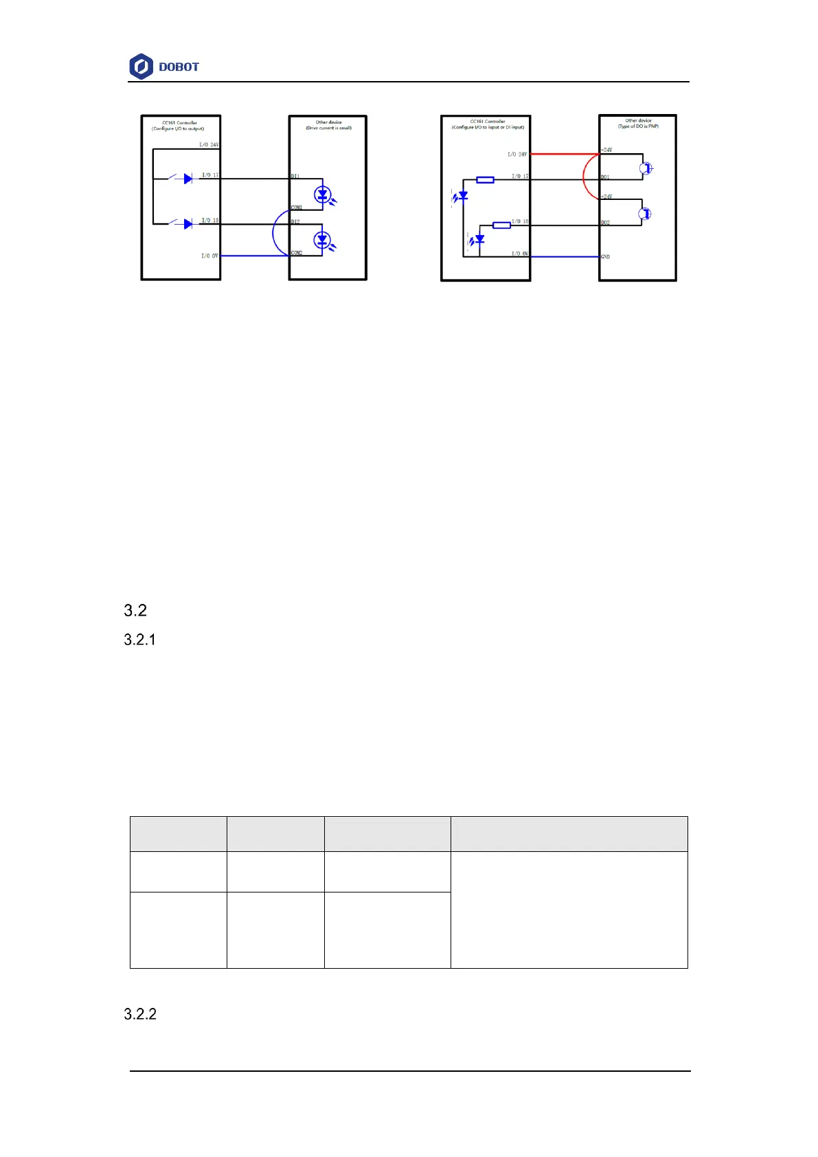
Figure 3.2 Controller I/O Connection
NOTE
The inner power supply and the outer power supply of every I/O can’t exceed
500mA.
The inner power supply and the outer power supply can’t exist at the same time, the
inner supply power outputs the max current which can’t exceed 2A; the outer power
supply outputs the max current which can’t exceed 4A.
At least one set of I/O 0V and 0V is short-connected, and at least one set of I/O 24V
and 24V is short-connected when IO is internally powered. At least one set of I/O
0V and I/O 24V is short-connected to external 0V and 24V when IO is externally
powered.
Emergency Stop I/O Description
User Emergency Stop
User emergency stop I/O is an emergency stop interface provided to users, and users can
connect external emergency stop devices. The interface description is as follows:
NOTE
The emergency stop I/O is located at the safety I/O plate in controller, if you need to use
those emergency stop I/O, please contact our technology support.
Table 3.2 User emergency stop I/O description
I/O28 and DI12, I/O29 and DI13 are
redundant circuits of the user emergency stop
interface. Any one of the disconnections will
cause the user emergency stop function to be
triggered
Protective Stop