Do you have a question about the Dobot Magician E6 and is the answer not in the manual?
Introduces functions, specifications, and installation of DOBOT Magician E6 robots.
Specifies target users like customers, sales engineers, and support staff.
Covers validity, responsibilities, and limitations of liability for robot use.
Explains hazard symbols and their meanings used in the document.
Provides essential safety instructions for operating the robot for the first time.
Outlines precautions for ensuring operator safety during robot system operation.
Details the emergency stop switch functionality and recovery procedures.
Lists main components and describes the physical build of the Magician E6 robot.
Explains the status indicators and buttons on the robot and their functions.
Details the PC and App requirements for controlling the Magician E6 robot.
Explains joint, user, and tool coordinate systems for robot operation.
Describes the robot's default zero-degree joint position and calibration.
Discusses shoulder, elbow, and wrist singularity points in robot arm configurations.
Provides physical dimensions and working space considerations for robot installation.
Details the mounting dimensions for the robot base.
Specifies the dimensions for the robot's base mounting plate.
Outlines the dimensions for the robot's end flange for tool attachment.
Describes the various ports and interfaces on the robot base.
Details the connection for the emergency stop switch.
Explains the digital input/output connections and wiring.
Details the pins and function of the encoder interface.
Describes the digital inputs and outputs for end effectors.
Specifies optimal environmental conditions for robot installation and operation.
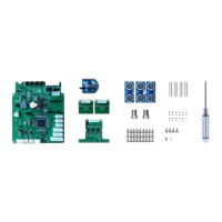
Guides users through the process of unpacking the robot and checking contents.
Covers standard and side mounting procedures and platform requirements.
Explains how to attach tools to the robot's end flange.
Details the procedure for connecting the robot's power and emergency stop cables.
Outlines the initial steps for debugging the robot arm after power-up.
Lists critical safety precautions for performing maintenance and repairs.
Details regular maintenance inspections and essential checks for robot performance.
Defines the warranty period, coverage, and claim procedures.
States Dobot's commitment to product improvement and disclaims responsibility for errors.
| Type | Desktop robotic arm |
|---|---|
| Max Payload | 0.5 kg |
| Degrees of Freedom | 6 |
| Power Supply | 100-240V AC, 50/60Hz |
| Communication | USB, Ethernet |
| Joint 4 Range | ±180° |
| Joint 6 Range | ±360° |
| Communication Interface | USB, Ethernet |
| Control Method | PC, Teach Pendant |
| Operating Temperature | 0-40 °C |
| Humidity | 20% - 80% RH (non-condensing) |