Dobot Magician E6 User Guide
Issue V1.3(2023-01-16) User Guide Copyright © Yuejiang Technology Co., Ltd.
25
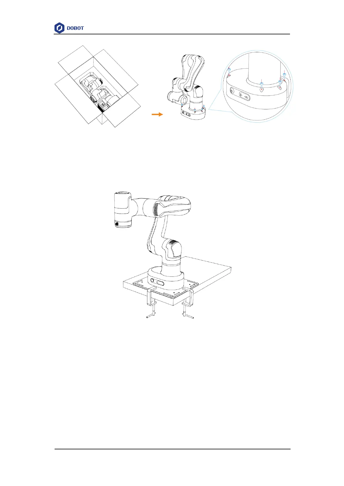
Figure 7.2 E6 installation steps
You can also fix the robot on the base plate, and fix the base plate on the installation platform
using M4 screws or G-type cramps (maximum clip distance: 55 cm). You can refer to 5.3Base plate
dimensions for the specific dimensions of the base plate. The G-clamp is recommended to be fixed
diagonally, as shown below.
Figure 7.3 G-type cramp
7.3.2 Tool installation
The end flange of the robot arm has four M6 threaded holes, which can fix the tool to the end
of the robot arm. In order to accurately adjust the position of the tool, you can also use the reserved
Φ6 positioning hole, and position it using pins. For specific dimensions, refer to 5.4Flange
dimensions.
 Loading...