Page 20
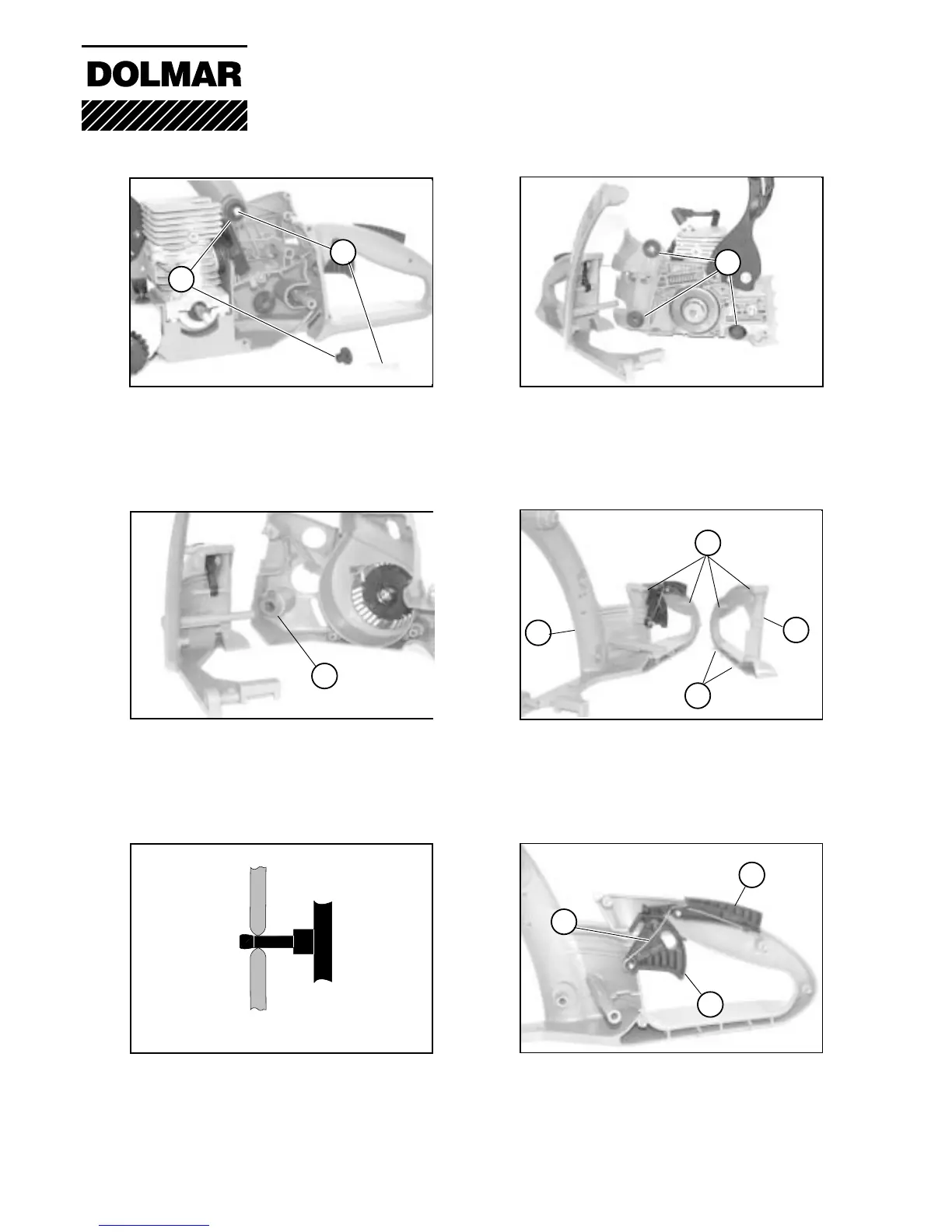
08-02 Removing the rubber buffer
Remove 2 screws (1) and sleeves (2).
Fold back handle to the side so that the
throttle linkage slides out of the throttle
guide.
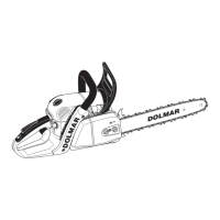
08-08 Dismantling the handle
The throttle grip (10) and catch lever (11)
are inserted in handle guides with a
spring (11).
1
1
08-02 Rubber buffers
3 hollow rubber buffers (4) on the clutch
side are inserted in the housing.
4
08-08 Dismantling the handle
The grip shell (6) is built together with the
handle (9) with 2 brackets (7) and pins (8).
Lever the housing apart from the inside.
5
5
7
6
9
11
10
12
08 Rubber buffer /handles
08-08 Dismantling the handle
The pivots of the grip are held tightly in
the sleeves. Increase leverage force
gradually until pivot clicks out. If brackets
or pivots break, replace housing.
08-02 Rubber buffers
On the magnet side, 1 hollow rubber
buffer (5) is inserted in the starter hous-
ing.