46
EN
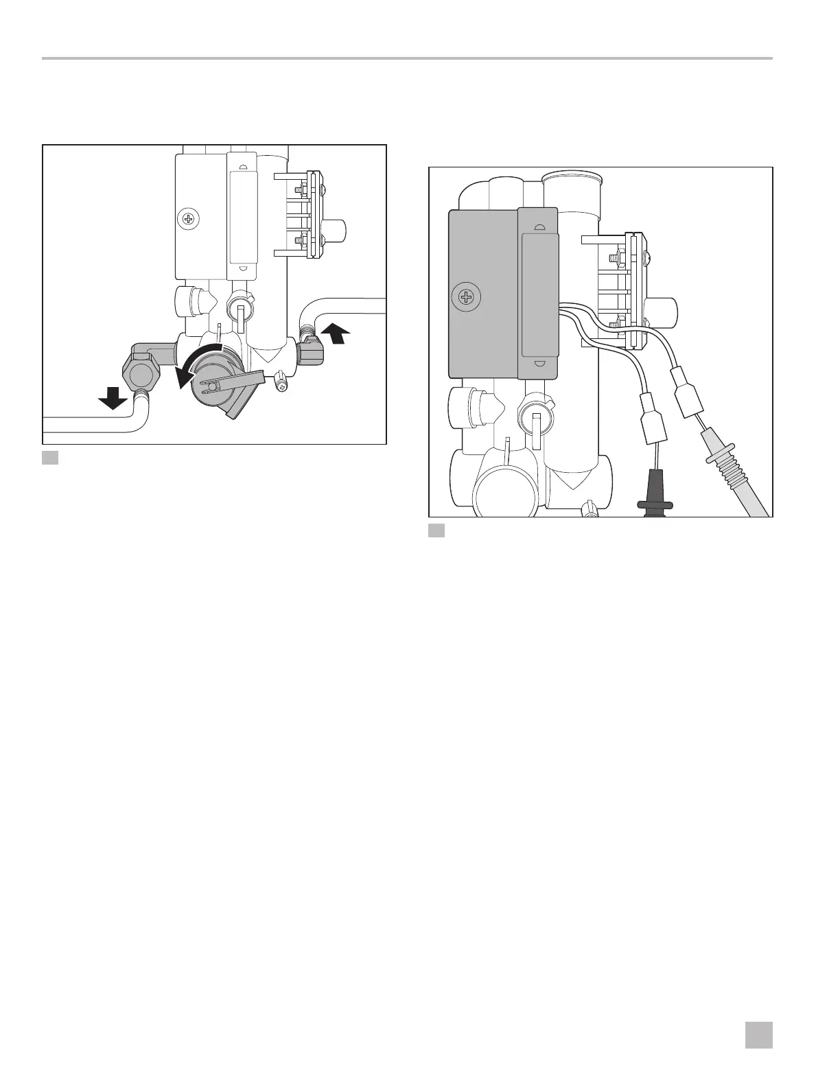
Service Procedures Water Heater
15. Remove the two mounting screws at the bottom of
the Water Heater casing that secure the modulating
valve to the Water Heater.
q
w
e
55 Disconnecting the Heat Exchange, P/T Valve, and Gas Line
q
Heat Exchange
e
Gas Line
w
P/T Relief Valve
16. Remove the modulating valve from the heat
exchanger.
17. Unscrew the P/T relief valve from the modulating
valve.
18. Remove the gas line from the modulating valve.
19. Remove the gas solenoid valve from the modulating
valve.
20. Reverse steps 1–19 to install the new modulating valve.
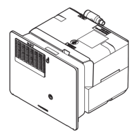
8.30 Performing a Reed Switch
Continuity Test
I
On Demand Models Only
56 Performing a Reed Switch Continuity Test
1. Place the control switch in the Off position.
2. Disconnect the two wires connected to the white
leads coming off of the reed switch.
3. Set your multi-meter to the Ohms resistance setting.
4. Attach the leads of the multi-meter, one to each lead
of the reed switch.
5. When the water is flowing at a rate of at least
0.8 gpm (3.0 lpm), you should have continuity
across the two leads of the reed switch.
I
Consult the operating manual for your multi-meter
for specific device function.
If the reading shows no continuity/open circuit, it
indicates a faulty reed switch.