- 11 -
INLET WATER SYSTEM
The inlet hose is connected to the inlet valve (normally closed). When the
outlet pressure sensor detects a low pressure (lower than the preset start pres-
sure), does the printed circuit board (PCB) energize the inlet valve, and the
valve opens (and the motor starts). The inlet valve includes a screen lter, for a rst
coarse particle ltration.
The inlet water ows to the integrated prelters that consist of two lter
cartridges, congured in
- serial ow (in most RO400-models) or
- parallell ow (in most RO600-models)
The purpose of the preltration is to protect the membrane , from mechanical and
chemical wearing. Better preltration gives longer service life of the membrane and
the product overall.
In serial ow does the preltration consist of one particle (sediment) lter and
one granulated activated carbon (GAC) lter . The particle lter removes par-
ticles larger than approx 10 µm. The carbon lter reduces Chlorine (Cl
2
), which is
important as the surface the membrane otherwise is damaged by Chlorine over time.
In parallell ow does the preltration consist of two identical carbon block lters
. The carbon block combines particle removal (larger than approx 5 µm) and
Chlorine reduction in one cartridge. The advantage of parallell ow is the lower
pressure drop, which becomes more important at high water ow (RO600 compared
with RO400). The ner particle ltration gives an improvement not only on the
membrane service life, but also the integrated high pressure pump .
3
1
H
F
In the following, the letters/numbers within brackets refer to gure.
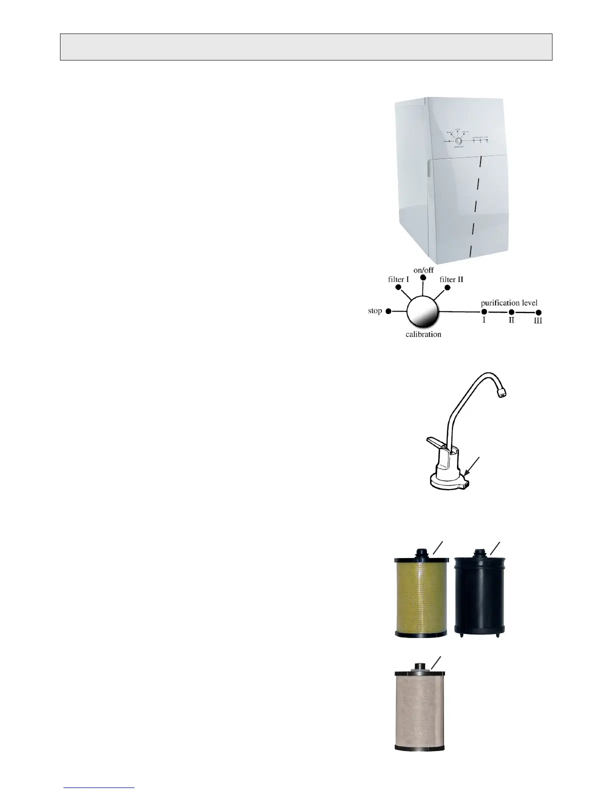
INDICATOR LIGHTS AND BUTTON
On the control panel of the water purier there are seven indicator lights (diods,
LEDs) and one push button, see g. F.
stop The product has stopped working. ‘stop’ alone or
with another diod gives an error code indicating the fault.
Change prelter/s/.
Too low pressure at the inlet, caused by blocked lters/s/,
low water supply pressure e.g.
on/off Indicates that the product is switched on (power on).
Change prelter/s/.
Filter/s/ consumed due to time in use.
Low purication level.
Good purication level.
High purication level.
calibration button Push button to
- calibrate levels for purication level,
- reset timer function of ‘lter II’,
- enter varios modes and control
functions useful during service.
For more information about indications, see “TROUBLESHOOTING”.
Indicator lights
An accessorie, see g. G, aimed for products installed under kitchen sink when
control panel is not always visable. It is intended to be mounted below the drinking
water faucet and connected to the indicator contact on the product backside.
- Green light indicate ‘purication level II / III’.
- Red light indicate ‘purication level I’
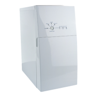
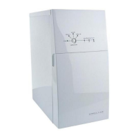
PRODUCT DESCRIPTION
2
1. Particle lter
2. Granulated Activated
Carbon (GAC) lter
3. Carbon block lter
G
Indicator lights