- 12 -
PRODUCT DESCRIPTION
PUMP SYSTEM
After the water has passed the prelters, it passes through the high pressure pump
. The high pressure pump is a vane pump, belt driven by a motor .
The pump is mounted in a special designed pump housing in brass. The
integration of several parts and components in the pump housing is the key to the
compact size of the product.
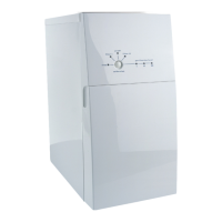
The high pressure pump increases the system pressure (pressure inside the mem-
brane pressure vessel , applied onto the membrane surface) up to a maximum
of approx. 15 bar. The system pressure can be measured according to g. I.
The system pressure is adjusted with the screw on top of the pressure regulation
valve. The position of the screw determines the tension of the spring loaded
piston against the system pressure. In case the system pressure exceeds the spring
load, will the valve act as a relief valve and lead back the water to the pump inlet.
The screw is adjusted to the correct position from the factory and should not be
changed unless the purpose is troubleshooting and the measures is fully under-
stood.
The regulation of the pressure is independant of inlet water pressure and tempera-
ture. Another feature is that the valve instantly reduces the system pressure, to
minimize the effect of water hammer, when a valve or faucet on the pure water hose
is closed.
MEMBRANE SYSTEM
Just before the pressurized water reach the membrane vessel it passes through the
loop pump , positioned on the same shaft as the high pressure pump. The loop
pump increases the ow rate across the membrane surface (cross-ow) by internal
recirculation. This is the key for the high performance: high water efciency (recov-
ery), high capacity and high purication efciency, still with good resistance against
scaling.
(For better understanding; there is a balance between good water efciency and the
risk to clog the membrane.)
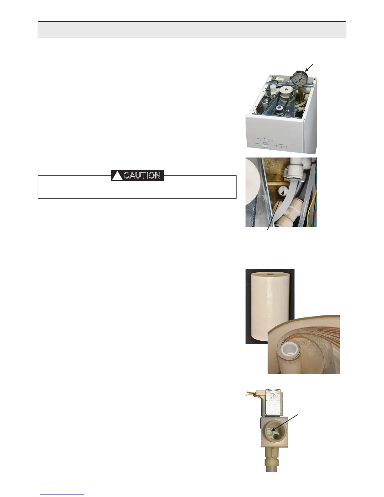
Inside the membrane pressure vessel, the water reaches the Reverse osmosis (RO)
membrane element, see g. . The type is spiral wound Thin Film Composite (TFC)
membrane.
Inside the membrane element the water can take three ways:
A certain proportion of the water passes through the membrane (or more accurate,
the membrane at sheet). The quantity depends on system pressure, temperature,
water quality and general performance of the membrane.
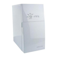
Another proportion of the water passes through the ush valve to the reject
water hose, routing the reject water to drain. The quantity of water ushed to drain
(during operation) is xed, and determined by a ow restrictor (small hole) in
the ush valve and the system pressure. The size of the hole depends on model.
Most of the water does however just cross the membrane surface into the loop pump
again, and recirculates.
I
K
Position for pressure gauge.
Adapter 1/8” thread.
Gauge should go up to 25 bar.
Membrane element.
Below opened to
show the membrane
components.
J
Flow restriction
If the screw of the pressure regulating valve is adjusted, do not forget to
.