- 34 -
2
3
SERVICE
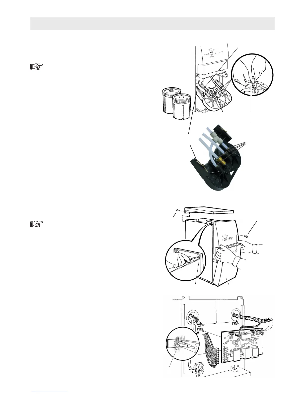
CHANGING TOP SECTION OF
PREFILTER ASSEMBLY
The numbers within brackets refer to g. .
Follow the instructions for “1. CHANGING FILTER CON-
TAINERS”, point 1-4, to remove both lter containers.
Press down the springs (2. ) through the opening in the
slide bar to pull out the top section.
Remove the hoses from the top section. The water ow 3.
conguration differs between RO400 and RO600:
Connect the hoses, removed in point 3) above, in the 4.
new top section.
Insert the old springs in the new top section and mount 5.
it in the slide bar.
Make sure the lters o-rings are correctly in the lter 6.
containers’ grooves. Consider changing the o-rings.
Screw the containers into the top section, Filter I on the 7.
left and Filter II on the right. Push the assembly to the
inner position and then tighten.
Connect to electricity and the product will start to ush.8.
Check for leakages.9.
Put back the top cover.10.
CHANGING PRINTED CIRCUIT BOARD
The numbers within brackets refer to g. Q.
Disconnect the water purier from electricity.1.
Remove the top cover (two screws at rear) 2. .
Remove the front cover (3. ).
Remove the control panel, two screws at top (4. ) and
two at bottom ().
Disconnect the connectors from the printed circuit 5.
board (PCB).
Remove the PCB from the locking supports on the 6.
casing, by pressing the retaining barbs of the snap-lock
together (4).
Install the new circuit board on the locking supports.7.
Reconnect connectors to the circuit board.8.
Put back the control panel, front cover and top cover.9.
The new PCB must be calibrated (paired) with sensors, 10.
see
“CALIBRATING PRESSURE SENSOR” and
“CALIBRATING CONDUCTIVITY SENSOR”.
P
1
a) Serial ow, RO400
Rubber hose (1) )
PE hose (2) ) to the pump inlet.
Move hose (3) 4) from the old to the new top section.
b) Parallell ow, RO600
All four hoses (1) ).
4
5
Serial ow,
RO400
Parallell ow,
RO600
Q
1
3B
2
4
3A