- 36 -
SERVICE
CHANGING PURIFIED WATER OUTLET
Disconnect the water purier from electricity.1.
Remove the top cover (two screws at rear).2.
Remove the 3/8” hose from the puried water outlet 3.
both in- and outside of the casing.
Remove the plastic nut holding the puried water outlet 4.
to the casing. Lift up the outlet from the casing.
Remove the outlet pressure sensor from the outlet and 5.
mount it on the new.
Attach the outlet to the casing using the plastic nut.6.
Ret the 3/8” hose, both in- and outside of the product.7.
Connect to electricity and the product will start to ush.8.
Check for leakages.9.
Put back the top cover.10.
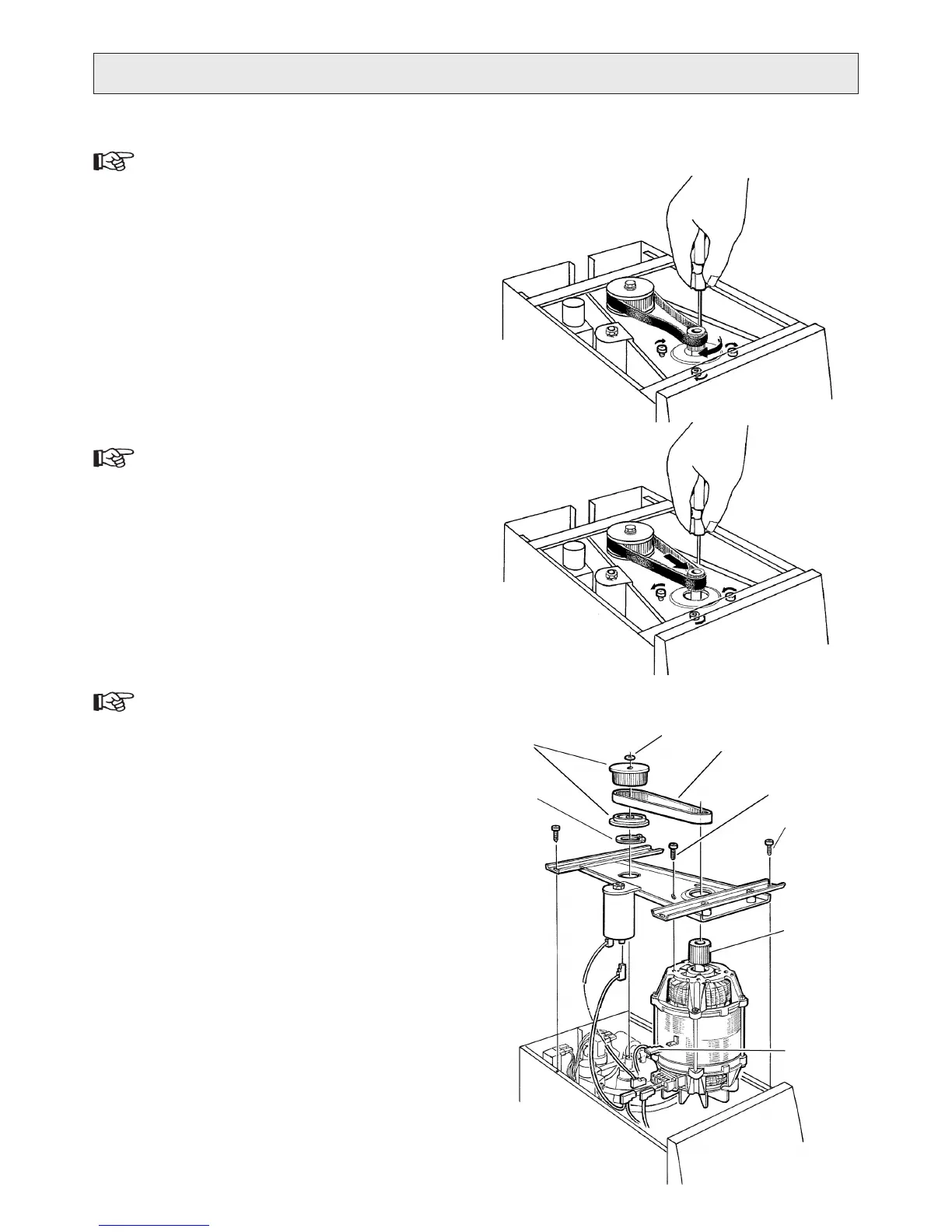
CHANGING DRIVING BELT
See g. S.
Disconnect the water purier from electricity.1.
Remove the top cover (two screws at rear).2.
Release the four screws holding the motor.3.
Turn the motor to slacken the driving belt and remove it.4.
Fit a new driving belt.5.
Turn the motor to stretch the belt, but not too hard.6.
Tighten the screws holding the motor.7.
Put the plastic foil back if it was removed in the rst place 8.
(purpose to collect dust from the belt on the motor plate).
Put back the top cover.9.
CHANGING MOTOR
The numbers within brackets refer to g. .
Disconnect the water purier from electricity.1.
Remove the top cover (two screws at rear).2.
Remove the screws holding the frames inside the casing 3.
(four screws) ().
Remove the plastic foil from the motor plate.4.
Release, but do not remove, the screws holding the mo-5.
tor to the motor plate (). Remove the driving belt ().
Remove the locking ring (6. 4) and then the pump driving
wheel () from the pump shaft.
Press down the wings of the insulating ring 7. and lift
the motor assembly upwards.
Disconnect the wires from the motor.8.
Remove the motor from the plate (four screws).9.
Use the screws to install the new motor on the motor 10.
plate, but do not tighten. The new motor should have a
driving wheel () premounted. If not, use the old wheel.
Reconnect the wires to the motor.11.
Lower the motor assembly into the product, align prop-12.
erly over the pump shaft. Make sure the 1/4” hose coil
is away from the motor and its fan.
Press the insulating ring gently in position on the the 13.
pump head.
Fit the pump driving wheel. Secure with the locking ring.14.
Fit the driving belt, stretch it (but not too hard) and 15.
secure with the screws holding the motor.
Attach the frames to the casing using the four screws.16.
Put the plastic foil back on the motor plate.17.
Put back the top cover.18.
1
2
3
5
6
7
Green/
Yellow
T
S
4