For all models:
Maximum bends (90º & 45º): 8 of 90º or 16 of 45º
Maximum Vertical length (meters): 25m (total amount of vertical meters plus horizontal meters)
Maximum Horizontal length (meters): 25m (total amount of vertical meters plus horizontal meters)
DO NOT USE AN UNLINED MASONRY CHIMNEY AS THE FLUE FOR THIS APPLIANCE.
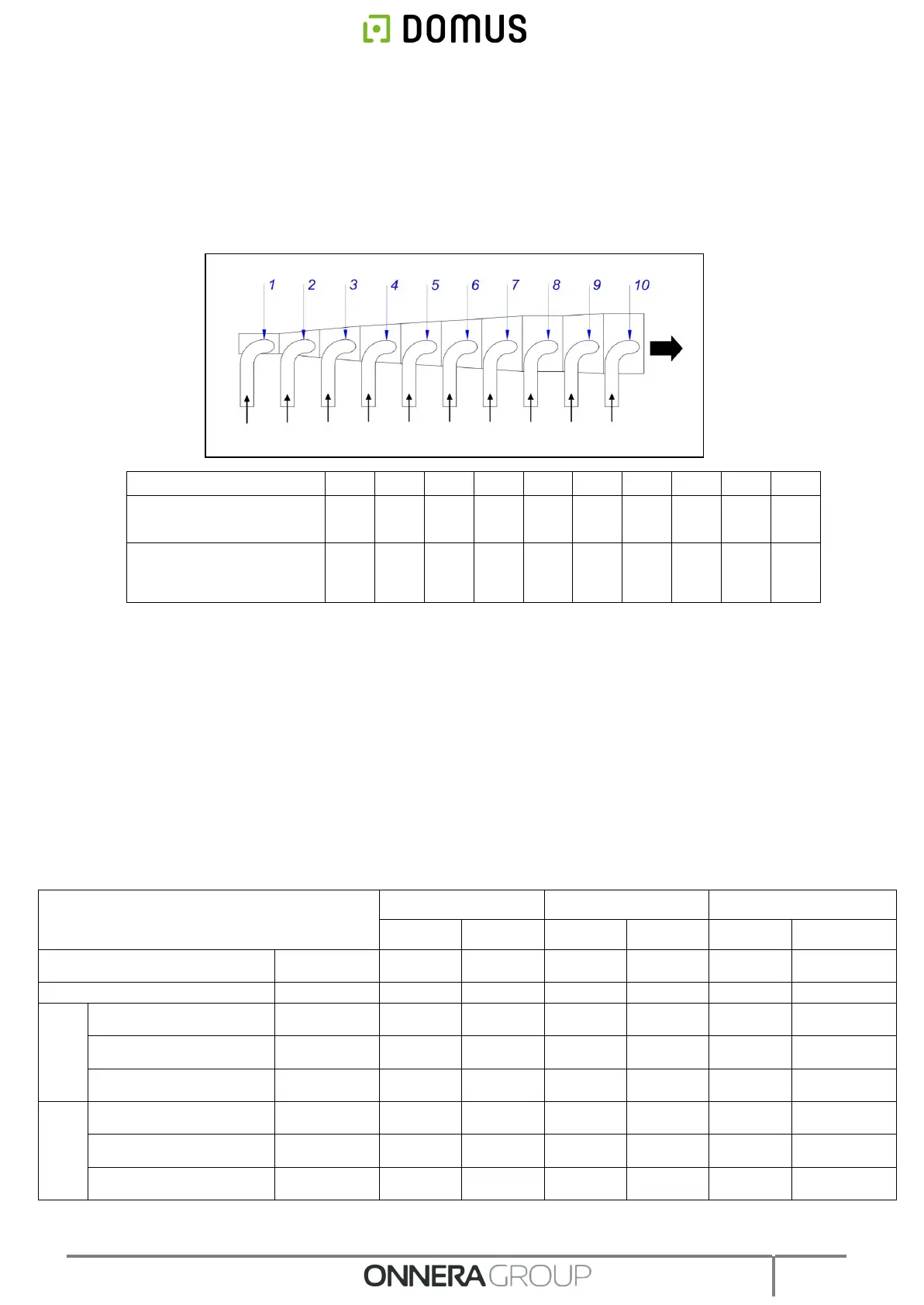
A table is given below listing the equivalent diameters required to connect various dryers to one common steam outlet
and the minimum area of the fresh air inlet (see section 3.3.1):
Diameter of the output
pipe (mm)
Minimum area of the
fresh air inlet to the
premises (m²)
3.4. Electrical connection
Make sure that the characteristics of the available power supply correspond to those of your dryer, indicated
on its identification plate, and that the cable section and other line accessories can supply the necessary
power.
The machine leaves the factory with the complete electrical installation, and therefore you will only have to
remove the cover on the back of the dryer and connect each of the terminals to the three phases L1, L2, L3,
neutral N and the ground connection to the connection terminals or the general switch.
A circuit breaker and differential switch MUST be inserted between the wiring and the mains, and the
sensitivity of the differential switch must be 300 mA. Higher sensitivity, for example 30 mA, common in
domestic installations may cause operating anomalies in the machine.
Connect the three phases, neutral on the connection terminals or general switch and the protection cable to
earth on the electrical components panel according to the following table (section in mm2).
Correct earthing is essential to guarantee the safety of users and correct operation.
(1) A supplement is necessary for 60 Hz.
Voltage and Standard Wiring
Cable section 230V 1N+G /
Fuse
Cable section 230V 3~+G /
Fuse
Cable section 400V 3N+G /
Fuse
Cable section 230V 1N+G /
Fuse
Cable section 230V 3~+G /
Fuse
Cable section 400V 3N+G /
Fuse