ONLY FOR TUMBLE DRYERS SOLD IN AUSTRALIA AND NEW ZEALAND:
This appliance must be installed by an authorized person in accordance with this instruction manual,
AS/NZS 5601-Gas installations (installation and pipe sizing), local gas fitting regulations, local electrical
regulations, local water regulations, local health regulations, Building Code of Australia, and any other
government authority.
The installer must test the operation of the appliance after installation.
3.6. Injector replacement
If the appliance is installed in a country where it is necessary to change the injector diameter or even to
install the appliance ready for operation with another type of approved gas, please call the technical
service to make the change.
Please follow the instructions below to change the gas supply from propane to natural gas.
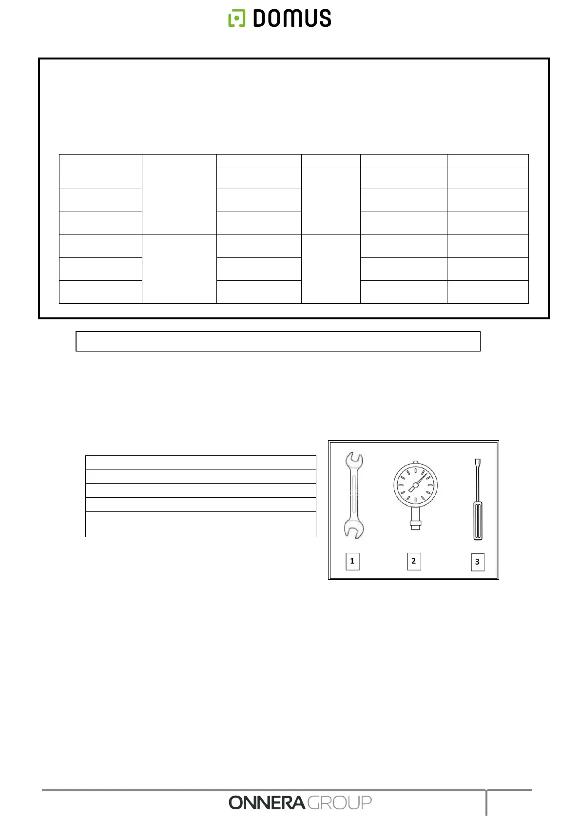
PROCEDURE:
All the dryers are fitted with a 3/4” “E” gas inlet. Never connect a pipe with an inner diameter less than
this.
1- Locate the Injector “D” on the left side of the valve covered by a metal plate. Unscrew the injector until it
comes out using the wrench no. 13.
2- Replace the injector with the one contained in the hanging bag.
3- Connect the gas input to the 3/4” “E” connection.
4- Loosen the bolt in opening "B" of the valve one turn in an anti-clockwise direction.
5- Connect the pressure gauge on opening "B" (scale of 0 to 100 mbar).
6- Remove the solenoid valve plug "C".
7- Regulate the gas inlet screw “C” until the required pressure is reached according to the table of gas types
and pressures. Do not over-tighten the Nylon bolt as there is a risk of breaking the internal spring and
causing fuel leaks.
8- Replace the solenoid valve plug "C".
9- Remove the manometer pipe.
10- Tighten bolt "B".
11- “A” Hole to measure supply pressure.
Natural gas injector (found in the BAG close
to the valve).
ONLY AUTHORISED SERVICE TECHNICIANS MAY CONVERT THESE APPLIANCES.