Donaldson Company, Inc.
32
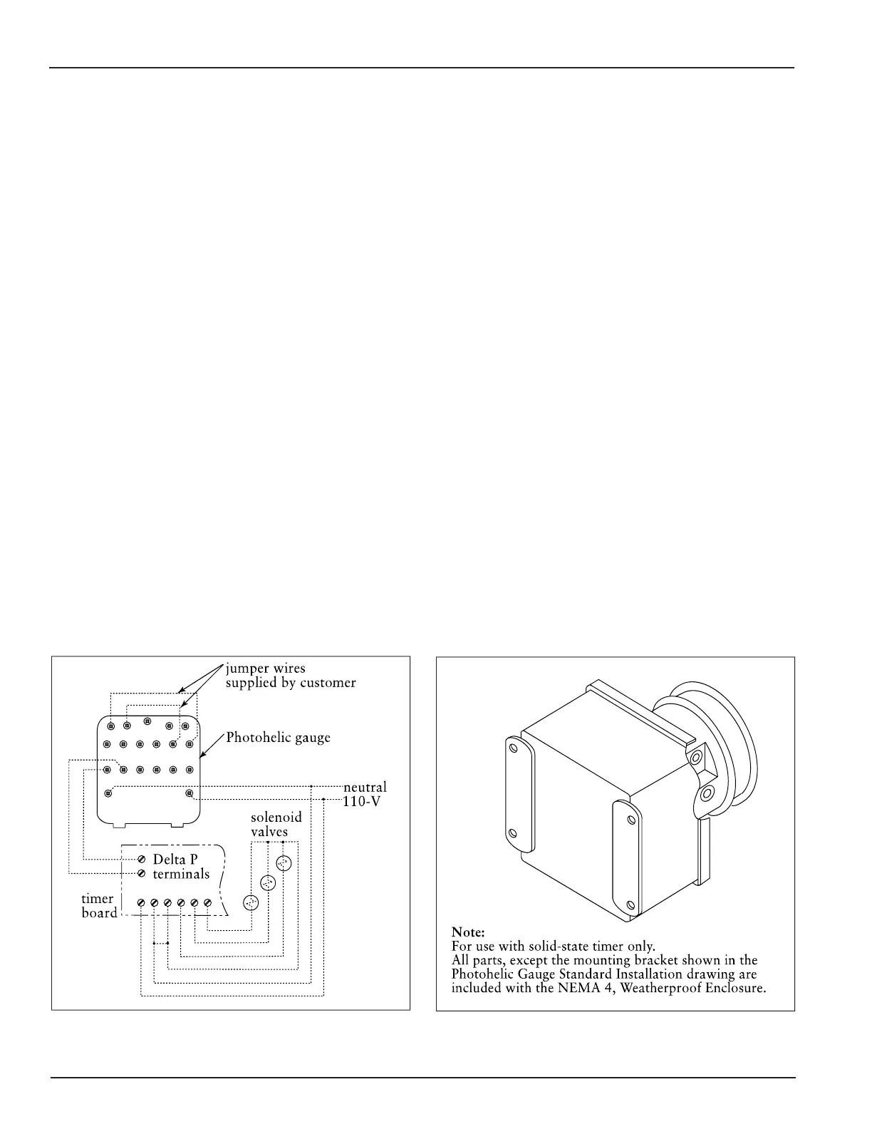
Photohelic Gauge in Optional NEMA 4
Weatherproof Enclosure
Photohelic Gauge Wiring Diagram
Photohelic Gauge
The Photohelic combines the functions of a
differential pressure gauge and a pressure-based
switch. The gauge function measures the pressure
difference between the clean- and dirty-air chambers
and provides a visual display of filter condition. The
high-pressure tap is located in the dirty-air plenum
and a low-pressure tap is located in the clean-air
plenum. The pressure-based switch function
provides high-pressure ON and low-pressure OFF
control of the filter cleaning system.
1. Choose a convenient, accessible location on or
near the unit for mounting that provides the best
visual advantage.
2. Mount the gauge to the remote panel or door
using the mounting ring, retaining ring, and four
#6-32 x 1 1/4-in screws. Do not tighten screws.
Connect two, 1/8-in NPT x 1/4-in OD male
adapters to the gauges high- and low-pressure
ports. Align the adapters to the 2.375-in hole in
the right-hand side of the mounting bracket.
Tighten screws.
0
0
WSP
GSQ
0
0
,-
03
'232'2'23'
'232'2'23'
3. On the back of the gauge, remove four #6-32 x
5/16-in screws and plastic enclosure. Set aside.
Add two jumper wires supplied by customer.
Remove the jumper from the pressure switch
located on the timer board, if equipped. Using
the 3/4-in conduit opening, wire the gauge as
shown. Reassemble and fasten the enclosure
securely.
4. Thirty-five feet of plastic tubing is supplied and
must be cut in two sections. Connect one section
of tubing from the gauges high-pressure port to
the pressure fitting located in the dirty-air
plenum. Connect remaining tubing from the
gauges low-pressure port to the fitting in the
clean-air plenum. Additional tubing can be
ordered from your representative.
5. Zero and maintain the gauge as directed in the
manufacturers Operating and Maintenance
Instructions provided.
6. To install the Photohelic Gauge mounted in a
NEMA 4, Weatherproof Enclosure, follow Steps
4 and 5.