c2
d
b2
e
c1
b1
a
f
*
12-24 x 3/4" R.H.P.M.S.
8-32 x 1/4" T.H.P.U.C.M.S.
c
b
a
d
e
15
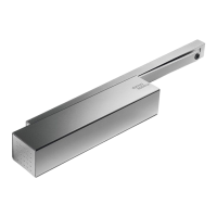
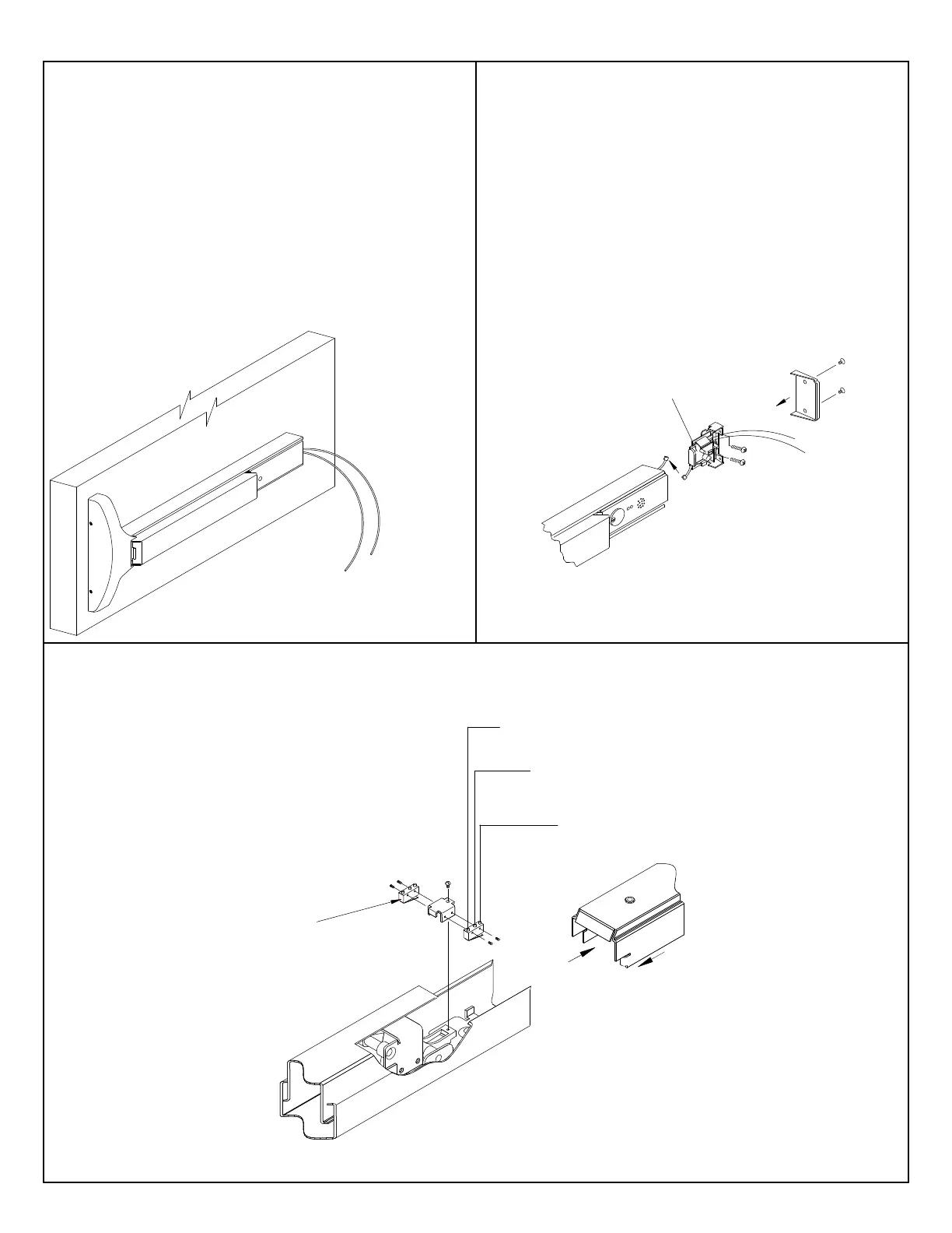
"MS" (MICRO SWITCH) OPTION:
"DWA" (DIRECT WIRED ALARM) OPTION:
"ES" (ELECTRIC LATCH RETRACTION) OPTION:
OPTIONS
(Non-polarized)
Green
White
(Polarized)
-
+
Positive
Negative
Red
Black
Electrically retracts latchbolt(s)
when energized by power supply.
REQUIRES DORMA PS501 POWER SUPPLY
AND ES105 POWER TRANSFER.
PS501 Will operate (2) "ES" 9600 exit devices,
but is capable of powering (2) additional devices
by installing the optional "ES-2" card.
*NOTE: Use caution when
cutting touch bar and rail to
length. Requires additional
hole see step 11.
NOTE: Touch bar must
be in dogged down po-
sition, to remove the
rear filler panel.
DWA
Battery Eliminator
(Standard mortise
cylinder supplied.)
Connected to outside power source.
12-24 Volt AC/DC Power Supply.
i.e. DORMA ES100 etc.,
Contact DORMA for other power
supplies available.
Refer to additional sheet
IAL9000 packed with device
for operation of alarmed
exit device.
SPDT, .5 amp
@ 28VDC max.
Green
Normally
Open
Black
Common
Red
Normally
Closed
*NOTE: Use caution when
cutting touch bar and rail to
length. Requries additional
hole see step 11.
"MS" option allows monitoring of touch
bar during normal operation, or can be
used as a signal switch for horn, light etc.
Comes standard with (2) two micro
switches. Both can be wired either
Normally Open or Normally Closed. Can
be added to device after installation.
Requires additional
hole see step 11.
Note: Normal switch position
shown, once installed normally
open and closed positions are
reversed.
 Loading...